Contoured golf club face

Inactive Publication Date: 2002-10-29
CALLAWAY GOLF CO
View PDF51 Cites 95 Cited by
  • Summary
  • Abstract
  • Description
  • Claims
  • Application Information

AI Technical Summary

Benefits of technology

The present invention comprises a contoured golf club face which addresses the problems previously described and a method of designing such a golf club face. The present contoured golf club face provides increased structural integrity for a golf club face of a given size and weight. The present contoured golf club face survives tests in which other club faces experience cracking and/or material failure. The present contoured golf club face does not adversely affect golf club performance, look, feel, and/or sound, but rather imp

Problems solved by technology

These large impact forces load the club face.
In the relatively thin faces of hollow metal wood type club heads and cavity backed iron type club heads these forces tend to produce large internal bending stresses.
These internal bending stresses often cause catastrophic material cracking which causes the club head to be unusable.
However, the addition of such a large amount of material to a club face generally adversely affects the performance of a club incorporating such a face.
The club performance is adversely affected by the overly heavy club head which has a mass center (i.e. center of gravity) which is too close to the club face thereby affecting optimum performance.
In addition, the feel and sound of a club incorporating such a face is also adversely affected by the large number of vibrations transmitted through the club and by the acoustic response of the club.
Adding ribs to the back surface of a face to stiffen the face has the benefit of stiffening without adding a significant amount of weig

Method used


Image

  • Contoured golf club face
  • Contoured golf club face
  • Contoured golf club face

Examples


Example

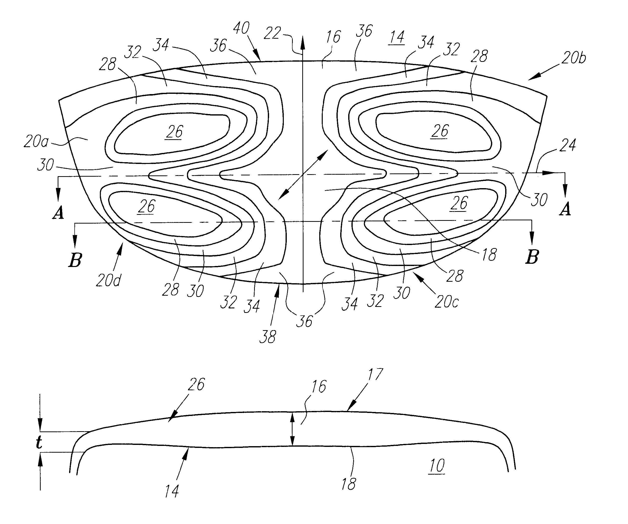
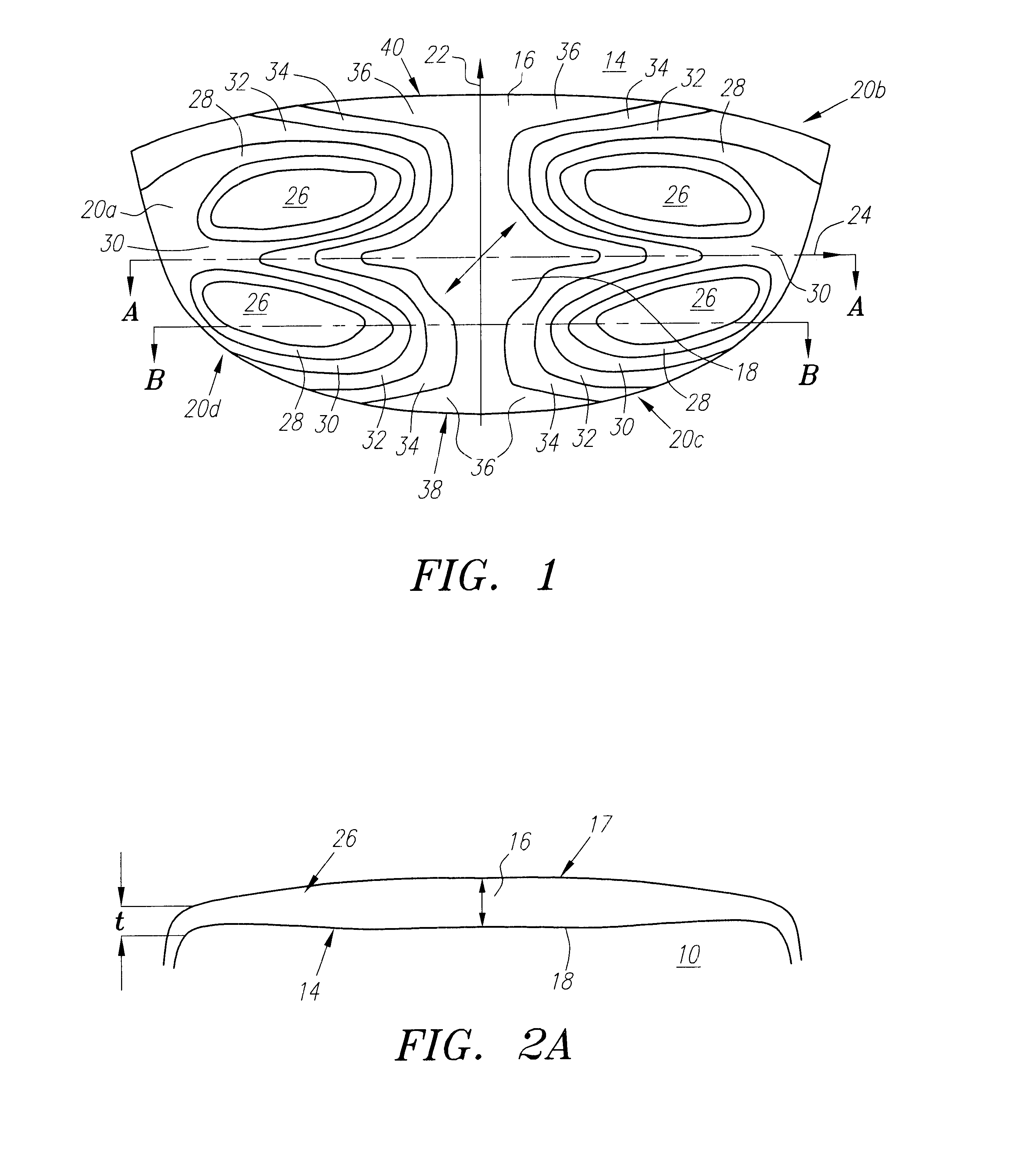
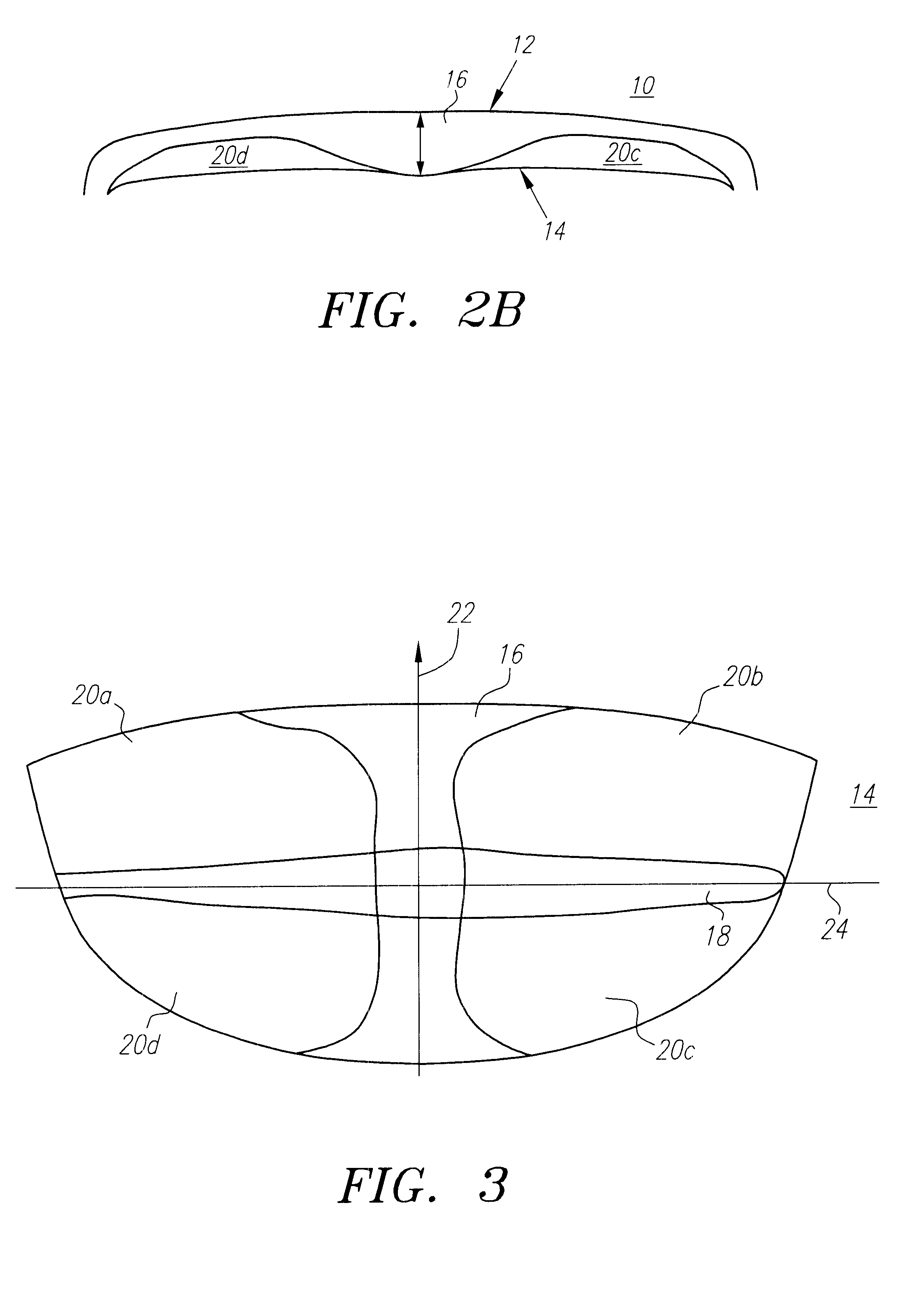
As is described above and shown in FIGS. 1-3, a golf club face 10 of the present invention comprises a substantially smooth front hitting surface 12 (shown in FIGS. 2A and 2B only), which may include score-lines (not shown), and a contoured back surface 14 which preferably comprises a vertical stiffening region 16 and a horizontal stiffening region 18 which together define four quadrants (or contoured regions) 20a-d on the face back surface 14.

As is shown in FIG. 1, the vertical stiffening region 16 preferably is generally located substantially along a vertical central axis 22 of the back surface 14 and has a certain preferable thickness T (shown in FIGS. 2A and 2B). The horizontal stiffening region 18 preferably is generally located along a horizontal central axis 24 of the back surface 14 (shown in FIG. 1) and has a certain preferable thickness T which preferably tapers to a thickness t toward extremities of the axis 24 (shown in FIG. 2A).

As is also shown in FIG. 1, the four quadr...


PUM


Abstract

A contoured golf club face provides increased structural integrity for a given weight and size is described and shown along with a method for its design. The contoured golf club face includes a vertical stiffening region, a tapered horizontal stiffening region, four similar contoured quadrants of increasingly thinning material toward the center of each quadrant, and thickening regions at face/sole and face/crown intersection regions. The thicknesses of adjoining regions are gradually blended to provide a smooth contoured surface. The present golf club face is light weight, is structurally resistant to impact deformation, is resistant to initial and long-term failure, has its mass center located at its sweet spot, exhibits inertial axes which are aligned with vertical and horizontal axes (i.e. primary club force directions: ball impact force and club centrifugal force directions), and produces acoustical tones. A club incorporating the present contoured golf club face may be provide a certain first acoustical sound when used to hit a ball with a certain first specific area of the face (e.g. the sweet spot or sweet spot region) and to provide a different second acoustical sound when used to hit a ball with an area of the face other than that first area (e.g. other than the sweet spot or sweet spot region). Thus, the present invention may be used to provide an educational tool for use in teaching and/or learning to consistently impact a ball on the optimal region of the club face.

Description

STATEMENT REGARDING FEDERALLY SPONSORED RESEARCH OR DEVELOPMENTNot ApplicableFIELD OF INVENTIONThe present invention relates to golf clubs, particularly to a golf club face which has a contoured surface opposite its hitting surface.BACKGROUNDGenerally, a golf club comprises a shaft portion, a head portion, and a grip portion. That part of the golf club head portion which outlines or defines a hitting surface is called a golf club face. See, e.g., R. Maltby, "Golf Club Design, Fitting, Alteration & Repair" (4th Ed. 1995). Generally, a club face abuts or is adjacent to both a crown (or top portion) of the club head and a sole (or bottom portion) of the club head.In hollow metal wood type club heads and cavity backed iron type club heads the golf club faces are preferably thin. Such golf club faces generally define two surfaces: a hitting (or front) surface and a back surface which is opposite the hitting surface.When the face of a golf club head strikes a golf ball, large impact force...

Claims


Application Information

Patent Timeline
IPC IPC(8): A63B53/04A63B69/36
CPCA63B53/04A63B69/3635A63B53/0466A63B2053/0408A63B2053/0462A63B2053/0454A63B53/047A63B2053/0458A63B60/00A63B53/0454A63B53/0458A63B53/0462A63B53/0408A63B53/08
Inventor KOSMATKA, JOHN B.
Owner CALLAWAY GOLF CO
Why Eureka
Try Eureka