Dual track assembly for refuse collection equipment

Inactive Publication Date: 2002-11-26
HEIL +1
View PDF13 Cites 7 Cited by
  • Summary
  • Abstract
  • Description
  • Claims
  • Application Information

AI Technical Summary

Benefits of technology

Accordingly, it is an advantage of the invention to provide a dual track assembly for refuse collection equipment that may pack refuse more efficiently and inexpensively. It also an advantage of the invention to provide an assembly that reduces the frictional forces and stress experienced by the components of the assembly while increasing the structural integrity of the refuse collection equipment. It is also an advantage of the invention to provide an assembly that minimizes the exposure of the components of the assembly to refuse and minimizes the unintentional release of refuse from the equipment. It is another advantage of a preferred embodiment of the invention to provide an assembly having hydraulic actuators that are arranged such that they extend during the packing process. It is still another adv

Problems solved by technology

These conventional assemblies, however, all suffer from a variety of disadvantages.
These assemblies, however, are complicated, costly, and difficult to assemble and disassemble.
These assemblies, however, increase the horizontal displacement of the assembly (e.g., the length of the overhang on a refuse truck) and the frictional forces and stress exerted on the track.
Also, the single straight track assemblies do not provide the sidewalls of the refuse collection equipment with an optimal amount of structural integrity.
In addition, the packer actuator and the track of the single straight track assemblies are not in substantial alignment.
As a result, these assemblies tend to direct refuse towards the roof of the storage compartment, and they do not efficiently utilize th

Method used


Image

  • Dual track assembly for refuse collection equipment
  • Dual track assembly for refuse collection equipment
  • Dual track assembly for refuse collection equipment

Examples


Example

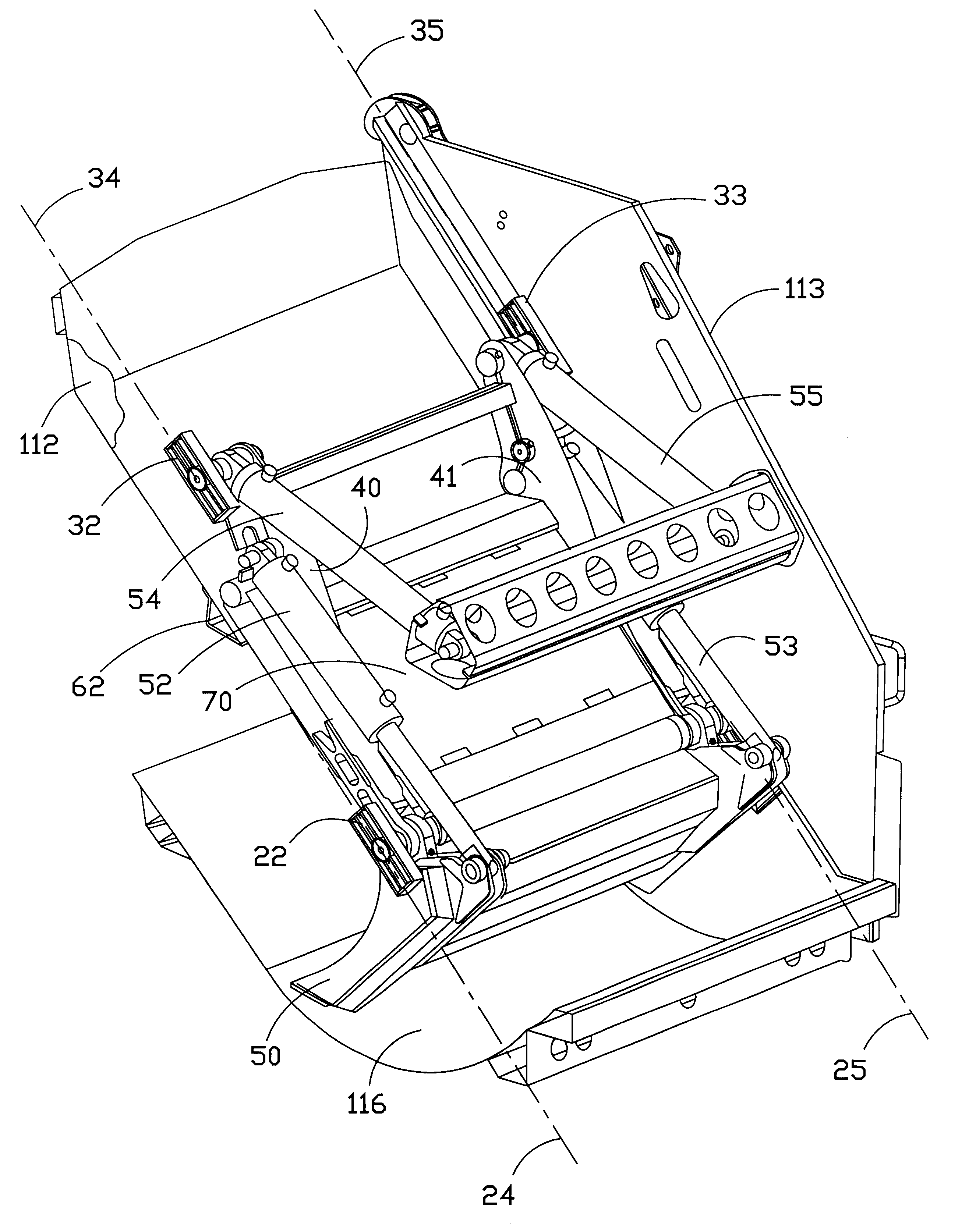
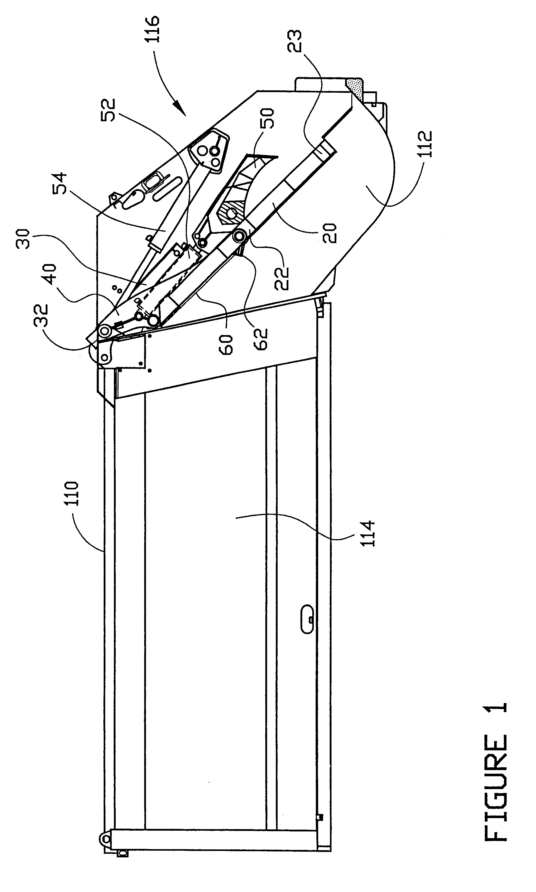
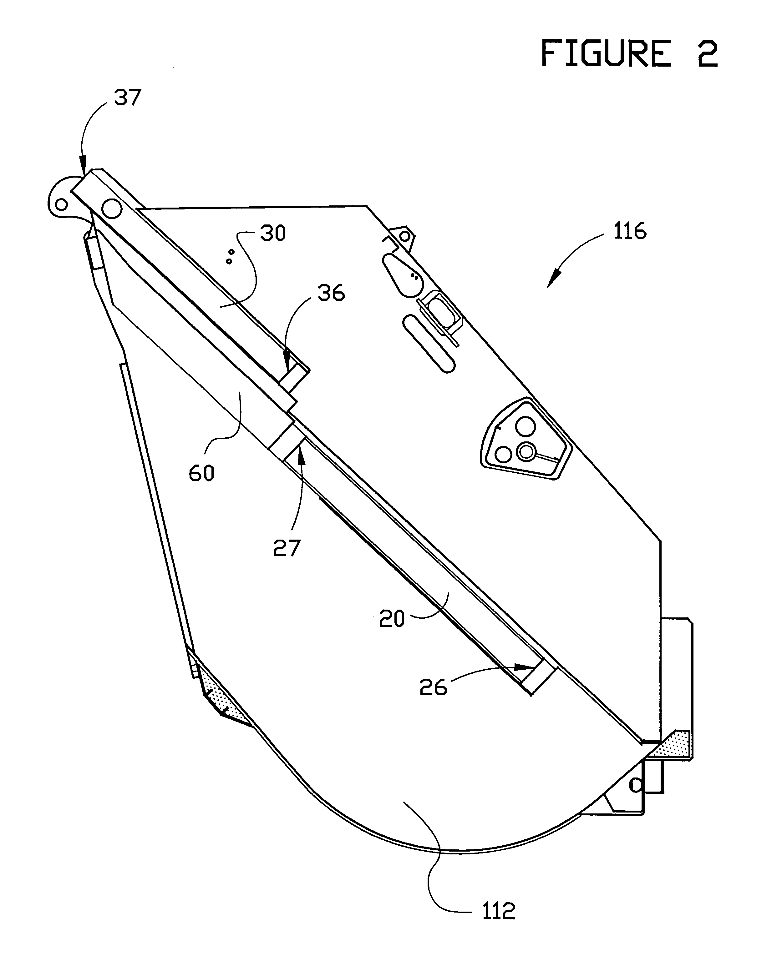
Referring now to the drawings, the preferred embodiments of the dual track handling assembly of the invention are illustrated in FIGS. 1 through 13. As illustrated in FIGS. 1, 2 and 4-7, the preferred embodiment of the assembly of the invention is adapted for use on rear-loading refuse collection truck 110 having first sidewall 112, a second sidewall 113 opposite the first sidewall (partially shown in FIG. 7), storage compartment 114, and hopper 116. The invention is adapted to move refuse from the hopper to the storage compartment of the truck. The preferred assembly comprises first lower track 20 on first sidewall 112, a second lower track on the second sidewall (not shown in FIG. 1), first lower track shoe 22 in first lower track 20, a second lower track shoe in the second lower track (not shown), first upper track 30 in first sidewall 112, a second upper track in the second sidewall (not shown), first upper track shoe 32 in first upper track 30, a second upper track shoe in the ...


PUM


Abstract

A dual track handling assembly is provided for refuse collection equipment having a hopper for receiving refuse, which hopper is defined in part by a pair of oppositely disposed sidewalls. The assembly includes a pair of lower tracks, each of which is mounted on a sidewall in a generally parallel disposition to the other. The assembly also includes a pair of upper tracks each of which is mounted on a sidewall in a generally parallel disposition to the other. The pair of lower tracks define a plane that is substantially parallel to a plane defined by the pair of upper tracks. The assembly also includes a pair of lower track shoes which move in the lower tracks and a pair of upper track shoes which move in the upper tracks. The assembly also includes a carrier having a lower track end that is attached to a lower track shoe, an upper track end that is attached to an upper track shoe, and a lower side that is substantially parallel to the tracks within which said lower and upper track shoes are received. The assembly also includes a blade that pivots between an open position and a closed position, a blade actuator, and a packer actuator that moves the upper track shoes in the upper tracks. The assembly also includes a deflector that is substantially parallel to the plane defined by the pair of lower tracks. The lower side of the carrier is adapted to substantially bear against at least a portion of the deflector.

Description

This invention relates generally to devices for moving refuse in refuse collection equipment. More particularly, this invention relates to an improved assembly for moving and packing refuse in an item of refuse collection equipment such as a rear-loading truck.BACKGROUND AND DESCRIPTION OF THE PRIOR ARTMany different devices have been used to move refuse from a hopper that is adapted to receive refuse to a storage compartment of a refuse collection truck. Typically, these assemblies comprise a blade for packing refuse, a carrier for moving the blade from an extended to a retracted position, and hydraulic cylinders for moving the carrier and the blade. These conventional assemblies, however, all suffer from a variety of disadvantages. For example, several conventional assemblies use a complicated system of links or links and tracks to move the blade from an open position to a closed position or from an extended to a retracted position. See, e.g., U.S. Pat. Nos. 2,619,216; 3,402,837; ...

Claims


Application Information

Patent Timeline
IPC IPC(8): B65F3/20B65F3/00
CPCB65F3/207
Inventor MCKINNEY, BOBBY
Owner HEIL
Why Eureka
Try Eureka