Mechanical sensor for a quick release hand brake

a technology of mechanical sensor and hand brake, which is applied in the direction of braking system, braking components, transportation and packaging, etc., can solve the problems of time-consuming and hazardous procedures for operators, and achieve the effect of reducing potential injuries

Inactive Publication Date: 2002-11-05
WESTINGHOUSE AIR BRAKE TECH CORP
View PDF8 Cites 31 Cited by
  • Summary
  • Abstract
  • Description
  • Claims
  • Application Information

AI Technical Summary

Problems solved by technology

However, a railroad operator often has to climb onto the railcar to visually determine that the hand brake is released before moving the train.
This procedure can be hazardous to the operator, and time-consuming.

Method used


Image

  • Mechanical sensor for a quick release hand brake
  • Mechanical sensor for a quick release hand brake
  • Mechanical sensor for a quick release hand brake

Examples


Embodiment Construction

Prior to proceeding to a more detailed description of the invention, it should be noted that identical components having identical functions have been clearly designated with identical reference numerals for the sake of clarity.

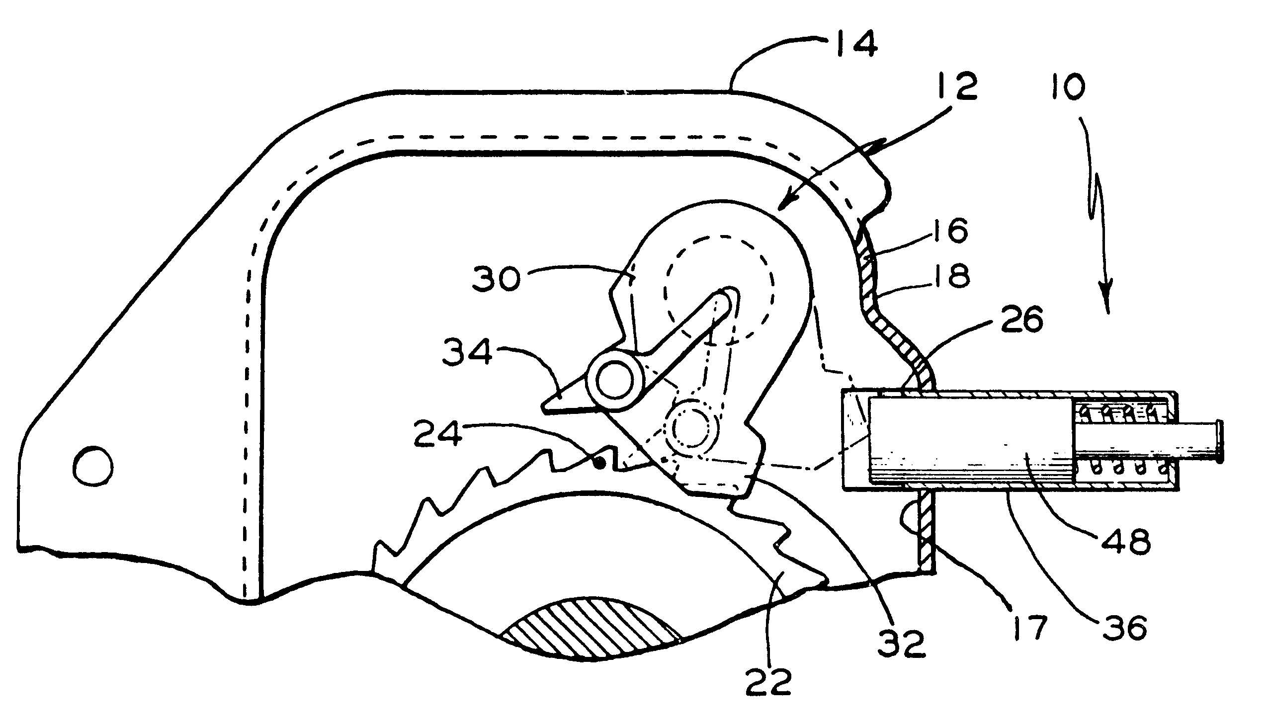
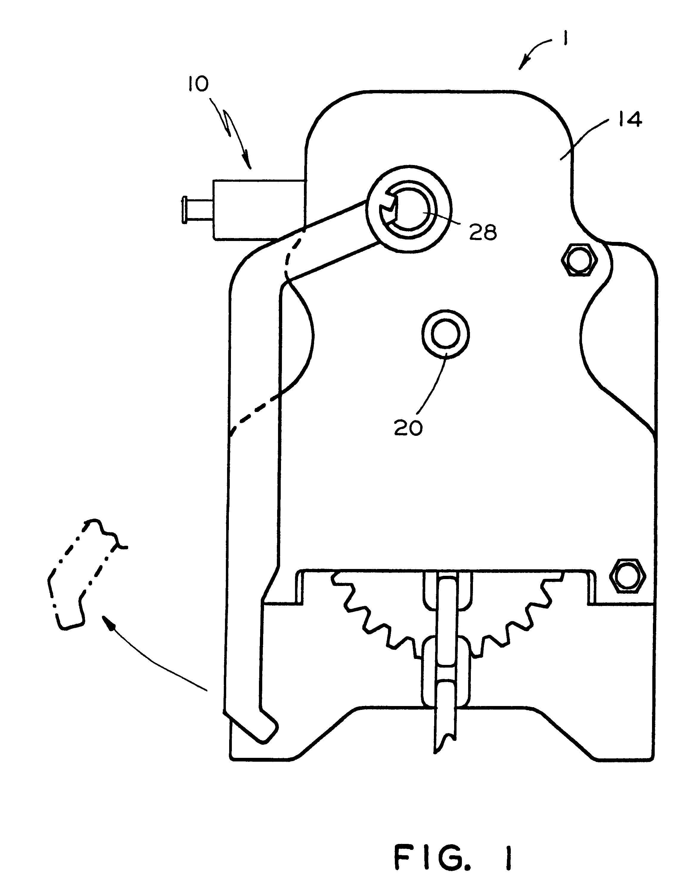
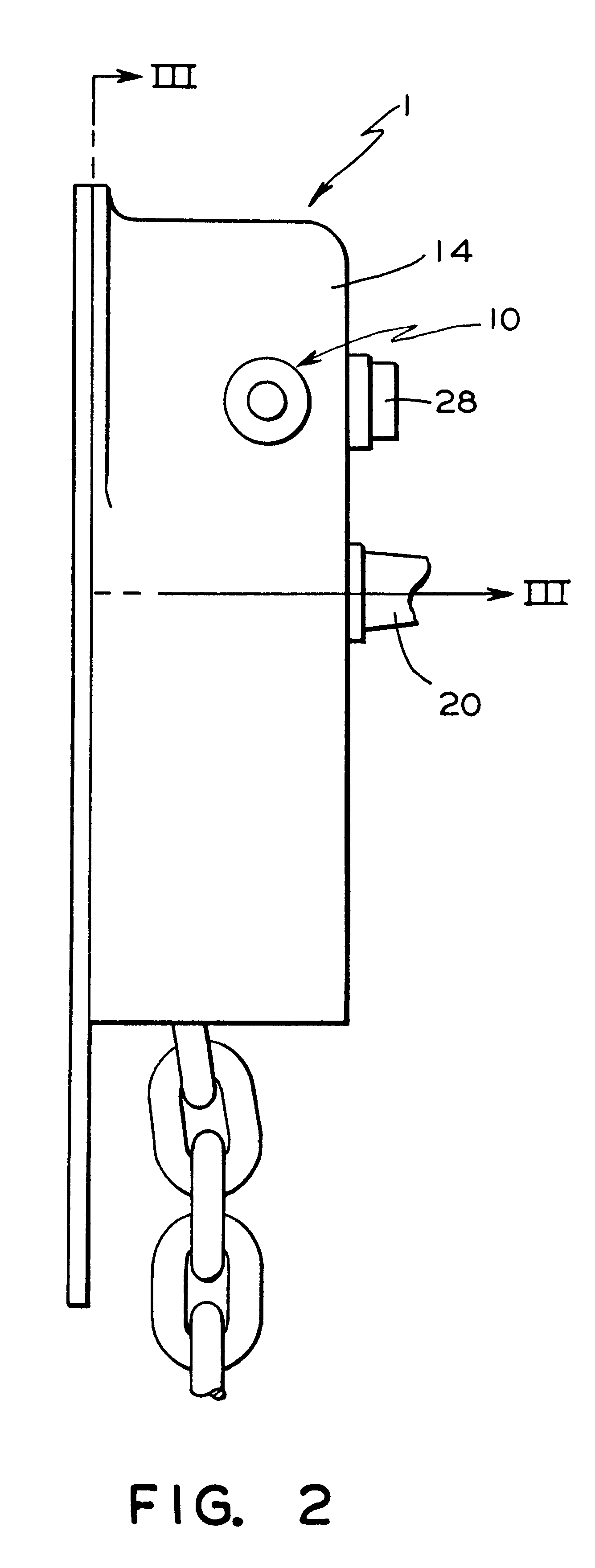
Now refer to FIGS. 1, 2, 3, 4, and 5 of the drawings. Illustrated therein is a mechanical sensor, generally designated 10, for a quick release mechanism, generally designed 12, for a railcar hand brake, generally designated 1, having a housing 14 equipped with a flexible clamp 26 mounted on an inside surface 17 of a wall 16 of the housing 14. A release shaft 28 has a member 30 disposed perpendicular to and about the circumference of the release shaft 28. A first element 32 is disposed on the member 30, which interposes with the flexible clamp 26 when the release shaft 28 is rotated to both achieve and maintain a full brake release. A second element 34 is disposed on the member 30 to engage a projection 24 on a ratchet wheel 22 when an operating shaft 20 of th...


PUM


Abstract

A mechanical sensor for a hand brake quick release mechanism having a housing, flexible clamp, and release shaft having a member with first and second elements. A housing member has open and closed ends. The open end is engageable with a housing outside wall at a point radially opposed to the flexible clamp. A first aperture formed through the closed end is in axial alignment with a second aperture through the housing wall and a third aperture through the flexible clamp. A first portion of the slidable member is disposed within the housing member. A second portion extends through the first aperture, and a portion of the first portion extends through the second and third apertures, engaging with the first element when the release shaft is rotated to achieve and maintain full brake release. A device is provided for urging the slidable member inwardly when the hand brake is applied.

Description

CROSS-REFERENCE TO RELATED APPLICATIONThe invention taught in the present application is closely related to the inventions taught in patent applications titled "Apparatus For A Quick Release Mechanism In A Railcar Hand Brake", having Ser. No. 09 / 664,212, filed on Sep. 18, 2000, now U.S. Pat. No. 6,364,428 and "Electronic Sensor For A Quick Release Hand Brake" filed concurrently herewith and having Ser. No. 09 / 876,337 filed on Jun. 7, 2001, now U.S. Pat. No. 6,364,069.These applications are assigned to the assignee of the present application. The teachings of these co-pending patent applications are incorporated herein by reference thereto.FIELD OF THE INVENTIONThe present invention relates, in general, to a mechanical sensor for a quick release mechanism for a railroad car vertical hand brake, and more particularly, to a mechanical sensor that provides a visual signal that the hand brake is in the released position.BACKGROUND OF THE INVENTIONPrior to the present invention, a railroa...

Claims


Application Information

Patent Timeline
Patent Type & Authority Patents(United States)
IPC IPC(8): B60T7/02B61H13/04B61H13/00B60T17/18B60T17/22
CPCB60T7/02B60T17/228B61H13/04
Inventor RING, MICHAEL E.BRABB, DAVID C.
Owner WESTINGHOUSE AIR BRAKE TECH CORP
Why Eureka
Try Eureka