Adjustable antenna mounting apparatus

Inactive Publication Date: 2002-11-12
BELLSOUTH INTPROP COR
View PDF22 Cites 18 Cited by
  • Summary
  • Abstract
  • Description
  • Claims
  • Application Information

AI Technical Summary

Benefits of technology

An antenna is a device used to send or receive electromagnetic waves forming telecommunications, radio, television, and other signals. Antenna assemblies typically in

Problems solved by technology

Such mounting brackets are typically not adjustable and therefore are not well-suited for affixing the antenna mast to a structure that lacks a vertically oriented surface.
For example, ex

Method used


Image

  • Adjustable antenna mounting apparatus
  • Adjustable antenna mounting apparatus
  • Adjustable antenna mounting apparatus

Examples


Embodiment Construction

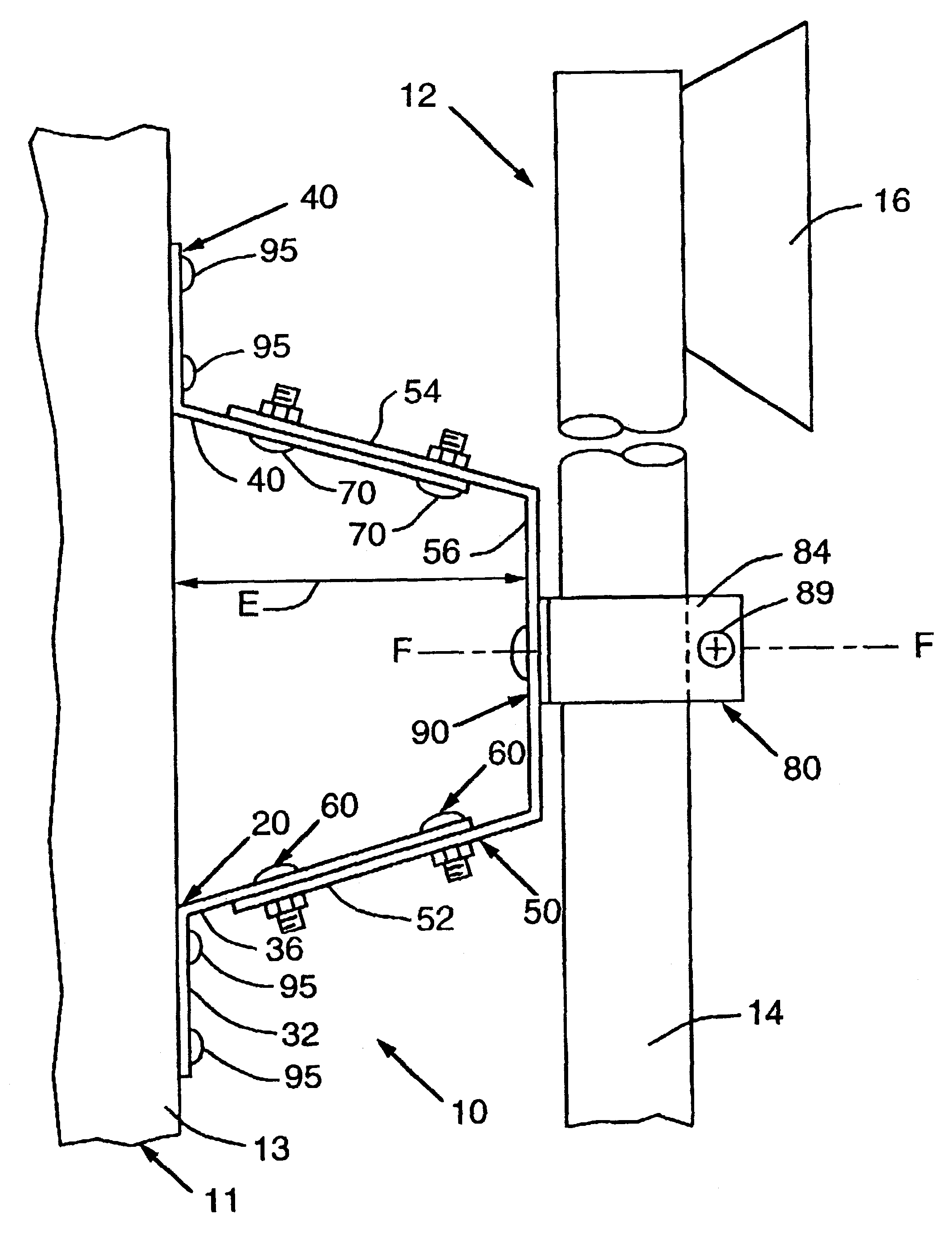
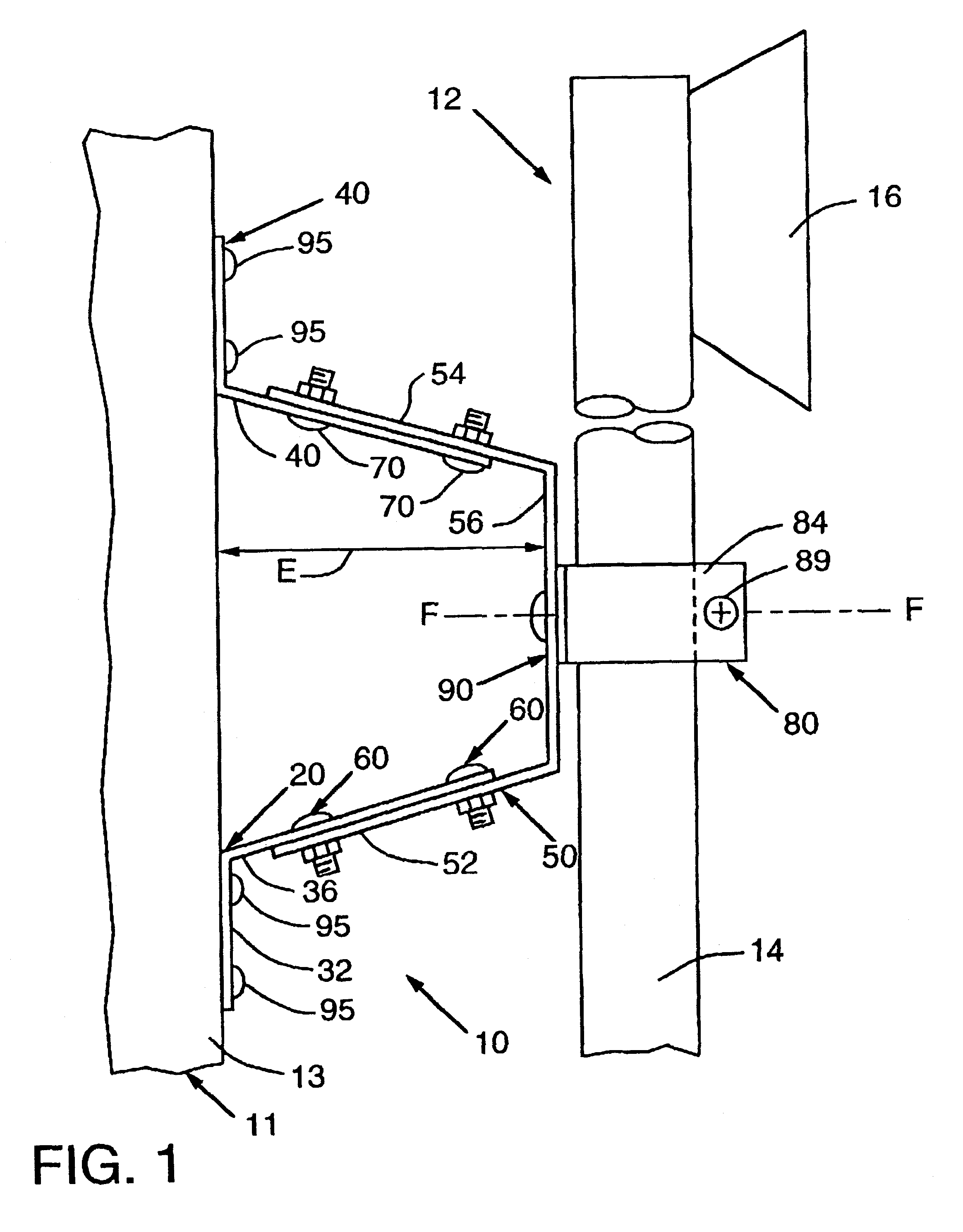
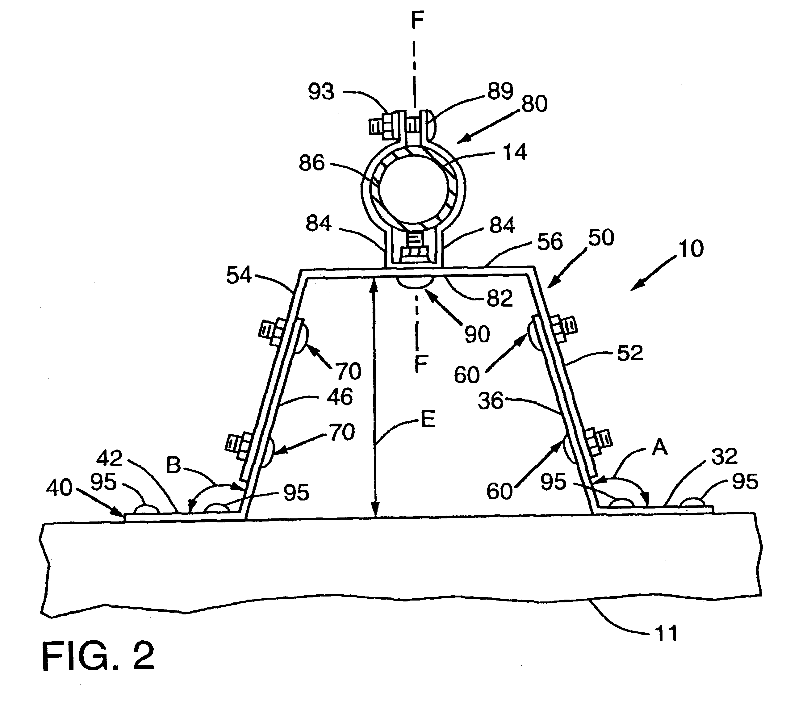
Referring now to the drawings for the purposes of illustrating the present embodiments of the invention only and not for the purposes of limiting the same, the Figures illustrate a mounting apparatus 10 for mounting the mast 14 of an antenna assembly 12 to a structure 11. As can be seen in FIG. 1, the antenna assembly 12 comprises a mast 14 and at least one signal receiver 16 that is affixed to the mast 14. A variety of different signal receivers (i.e., telecommunications, radio, television, microwave, etc.) are known in the art and, therefore, the construction of receiver 16 and its attachment to mast 14 will not be discussed herein. The skilled artisan will also appreciate that the mast 14 may comprise a metal pipe or other elongated structure suitable for supporting one or more receivers 16. While the mast 14 is shown herein as having a circular cross-sectional shape, it will be readily appreciated that the subject invention may be employed to support a variety of different mast ...


PUM


Abstract

An apparatus and method for rigidly supporting an antenna mast or other object relative to a structure in a desired position. The apparatus may comprise a first bracket that is affixable to the structure and a second bracket that is slidably affixed to the first bracket and capable of being locked in a desired position relative to the first bracket. A mast-supporting or object-supporting collar or clamp may be rotatably and slidably affixed to the second bracket and is capable of being locked in a desired position relative to the second bracket.

Description

Not applicable.FEDERALLY SPONSORED RESEARCHNot applicable.1. Field of the InventionThe subject invention relates to mounting devices and, more particularly, to devices for mounting an antenna mast to a variety of different objects and structures.2. Description of the Invention BackgroundAn antenna is a device used to send or receive electromagnetic waves forming telecommunications, radio, television, and other signals. Antenna assemblies typically include a signal receiver that is mounted to a pole or "mast" that is oriented in an elevated position above ground level to improve the receiver's line-of-sight range.The antenna mast may be mounted to a variety of different elevated structures such as buildings, poles, towers, trees, etc. to improve the receiver's line-of-sight. To optimize the antenna's reception and transmissibility such that a clear signal is received or sent, the antenna must be precisely positioned or "tuned". Tuning involves the manipulation and alignment of the re...

Claims


Application Information

Patent Timeline
IPC IPC(8): H01Q1/12
CPCH01Q1/12H01Q1/1207
Inventor SAWYER, CHARLIE C.
Owner BELLSOUTH INTPROP COR
Why Eureka
Try Eureka