Sampling device for water conservancy project river water detection

A technology of water conservancy projects and sampling devices, applied in the direction of sampling devices, etc., can solve the problems of high sampling difficulty, inconvenient use, and high difficulty in taking water from the center of the river channel

Inactive Publication Date: 2021-03-19
秦文
View PDF0 Cites 0 Cited by
  • Summary
  • Abstract
  • Description
  • Claims
  • Application Information

AI Technical Summary

Problems solved by technology

[0003] Existing river water sampling devices generally use the pump body to place the water intake pipe in the river to take water. First of all, it is difficult to sample water at different depths...

Method used


Image

  • Sampling device for water conservancy project river water detection
  • Sampling device for water conservancy project river water detection
  • Sampling device for water conservancy project river water detection

Examples


Embodiment 1

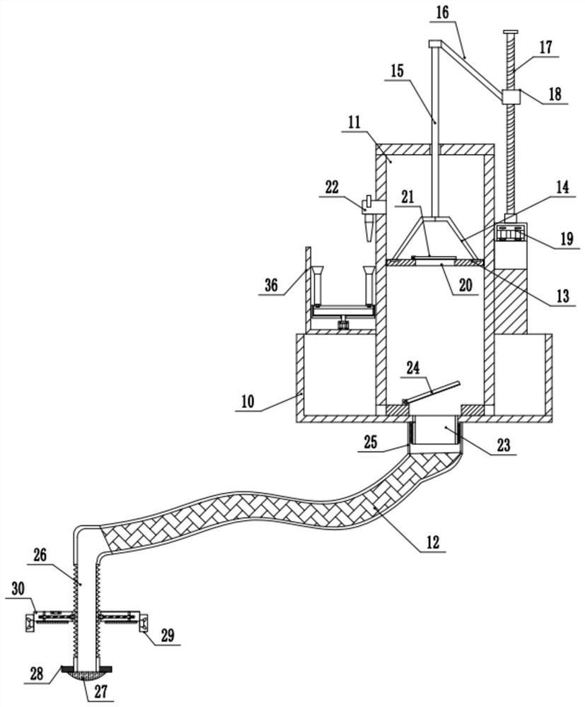
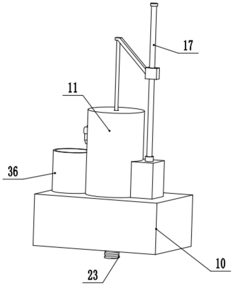
[0023] see Figure 1-2 , a water conservancy engineering river water sampling device, comprising a base 10, a water intake tube 11, an output pipe 22, and a water inlet tube 23; a group of vertical water intake tubes 11 are fixedly installed in the middle of the base 10, and the bottom of the water intake tube 11 communicates downward There is a threaded water inlet pipe 23 on the outside, and a group of externally threaded cylinders 25 with a folded pipe 12 connected to the bottom are provided on the water inlet pipe 23 . The upper part of the left side wall of the water-taking cylinder 11 communicates outwardly with an output pipe 22 of L-shaped structure, and the outer bottom end of the output pipe 22 is configured as a tapered structure. A group of transverse piston plates 13 are slidably connected to the middle part of the water intake cylinder 11, and a through hole 20 penetrating up and down is opened in the middle part of the piston plate 13, and a group of movable cov...

Embodiment 2

[0026] refer to Figure 4 , on the basis of Embodiment 1, the top of the base 10 below the output pipe 22 is fixedly installed with a group of water collection tanks 36 with upper openings, and a group of support grooves 39 are fixedly installed inside the water collection grooves 36, and the upper side of the support grooves 39 A group of rotating bases 38 are connected to the inner rotation, and the bottom middle part of the rotating base 38 passes through the support groove 39 vertically downwards and is rotatably connected with a group of servo motors 40 fixed on the inner bottom of the water collection tank 36. The top edge of the rotating base 38 is set There is a circle of water collecting pipe 37, and the water collecting pipe 37 rotated to the rightmost position of the swivel seat 38 is directly below the output pipe 22. In order to facilitate the installation and disassembly of the water collecting pipe 37 and the swivel seat 38, a group of bayonet pins are installed...


PUM


Abstract

The invention relates to the technical field of water conservancy projects, and discloses a sampling device for water conservancy project river water detection. The device comprises a base, a water taking cylinder, an output pipe and a water inlet pipe; a set of transverse piston plates are slidably connected to the middle of the water taking cylinder, a through hole penetrating up and down is formed in the middle of each piston plate, a set of first movable cover plates are hinged to the left side of the top of each through hole, a set of connecting frames with the cross sections being of a T-shaped structure are fixedly installed at the tops of the piston plates, and a set of vertical lifting rods are fixedly connected to the tops of the connecting frames. The upper sides of the liftingrods movably penetrates through the top of the water taking cylinder, the top ends of the lifting rods are fixedly connected with a set of nuts towards the lower right side through connecting rods, and the nuts are slidably connected to a ball screw arranged on the right side of the water taking cylinder; a group of second movable cover plates are hinged to the left side of the inner bottom of thewater taking cylinder on the upper side of the water inlet pipe; the bottom end of a folding pipe communicates with a set of vertical telescopic pipes, and a set of horizontal floating plates are arranged in the middles of the telescopic pipes.

Description

technical field [0001] The invention relates to the technical field of hydraulic engineering, in particular to a sampling device for detecting river water in hydraulic engineering. Background technique [0002] Water conservancy projects are projects built to control and allocate natural surface water and groundwater to achieve the purpose of eliminating harm and rejuvenating profits. Also known as water engineering. Water is an indispensable precious resource for human production and life, but its natural state does not fully meet human needs. In order to test the water quality of the river water, it is necessary to sample the river water frequently. [0003] Existing river water sampling devices generally use the pump body to place the water intake pipe in the river to take water. First of all, it is difficult to sample water at different depths, and for some rivers with wider channels , It is more difficult to take water in the center of the river, and the existing wat...

Claims


Application Information

Patent Timeline
IPC IPC(8): G01N1/14
CPCG01N1/14
Inventor 秦文
Owner 秦文
Why Eureka
Try Eureka