Drilling tool including a shank and a cutting body detachably secured thereto

a drilling tool and cutting body technology, applied in the field of drilling tools, can solve the problems of inability to form chip-forming edges, inability to integrate the tool shaft with the wearing part of the tool, and inability to drill holes

Inactive Publication Date: 2002-11-19
SANDVIK INTELLECTUAL PROPERTY AB
View PDF14 Cites 65 Cited by
  • Summary
  • Abstract
  • Description
  • Claims
  • Application Information

AI Technical Summary

Benefits of technology

The present invention aims at obviating the above-mentioned shortcomings of previously known drilling tools having replaceable cutting bodies and at providing an improved drilling tool. Therefore, a primary aim of the invention is to provide a drilling tool which with simple and few means can safeguard the cutting body of the tool on the shaft in a centered state which in a reliable manner is retained during the cutting operation. An additional aim is to create a drilling tool, the cutting body of which can be assembled and disassembled, respectively, in a simple and fast manner. Another aim is to create a drilling tool, the cutting body of which is self-centering inasmuch as the cutting body in connection with the drilling operation is brought automatically to assume the correct position also in such cases as when the cutting body is assembled initially in an incorrect manner. In one particular aspect, the invention also aims at providing a drilling tool having an improved cooling ability.

Problems solved by technology

In modern machine tools, the tool shafts are so sophisticated and expensive that they, for economic reasons, are no longer integrated with the wearing part of the tool, namely the cutting body, to form a single tool which has to be discarded when the cutting body has worn out.
In other words, it is profitable to make the actual cutting body as a detachable unit, which can be replaced, while the expensive shaft may be used for a long time.
A serious disadvantage with this design, however, is that chip-forming edges cannot be formed in the center area of the front or top surface of the cutting body, and therefore the cutting body cannot be designed for drilling purposes.
For this reason, previously known drilling tools having replaceable cutting bodies are structurally complicated and demand a plurality of details, such as screws, springs or drawbars for the fastening of the cutting body.
This means, in practice, that the assembly as well as the disassembly of the cutting body become complicated and time-consuming at the same time as difficulties arise in centering the cutting body in relation to the shaft in an exact manner.
Furthermore, the fixation becomes unreliable inasmuch as the cutting body may be dislodged from an initially centered position during operation.

Method used


Image

  • Drilling tool including a shank and a cutting body detachably secured thereto
  • Drilling tool including a shank and a cutting body detachably secured thereto
  • Drilling tool including a shank and a cutting body detachably secured thereto

Examples


Embodiment Construction

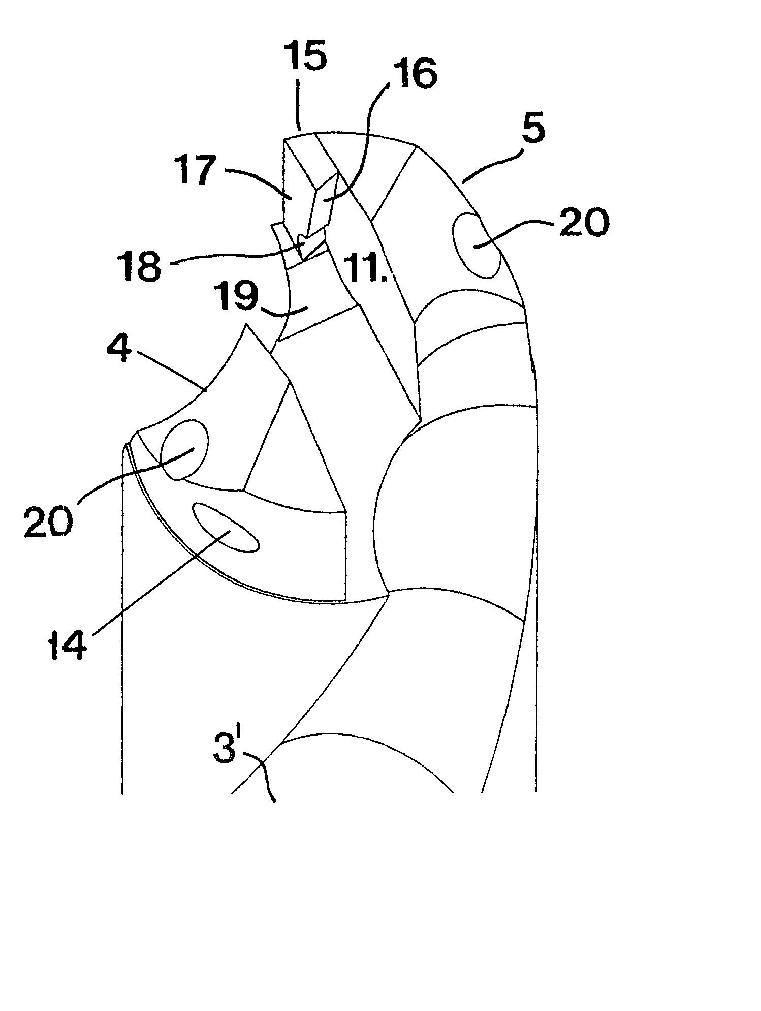
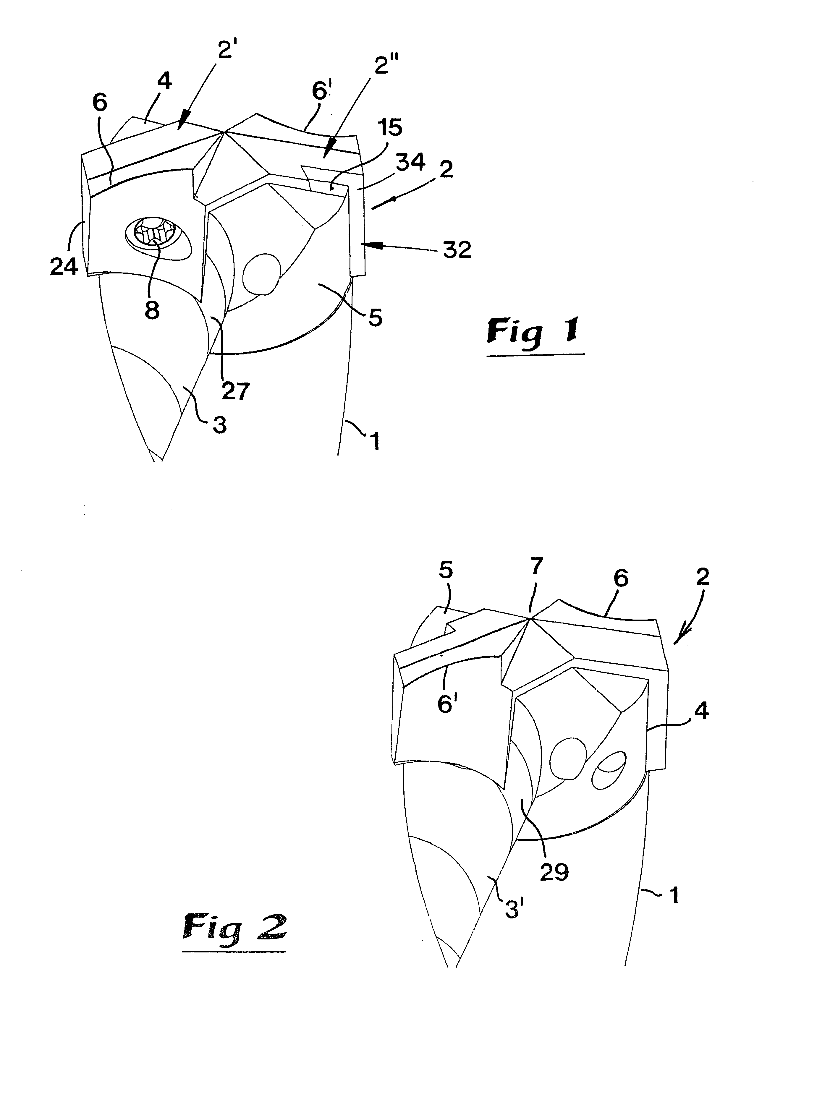
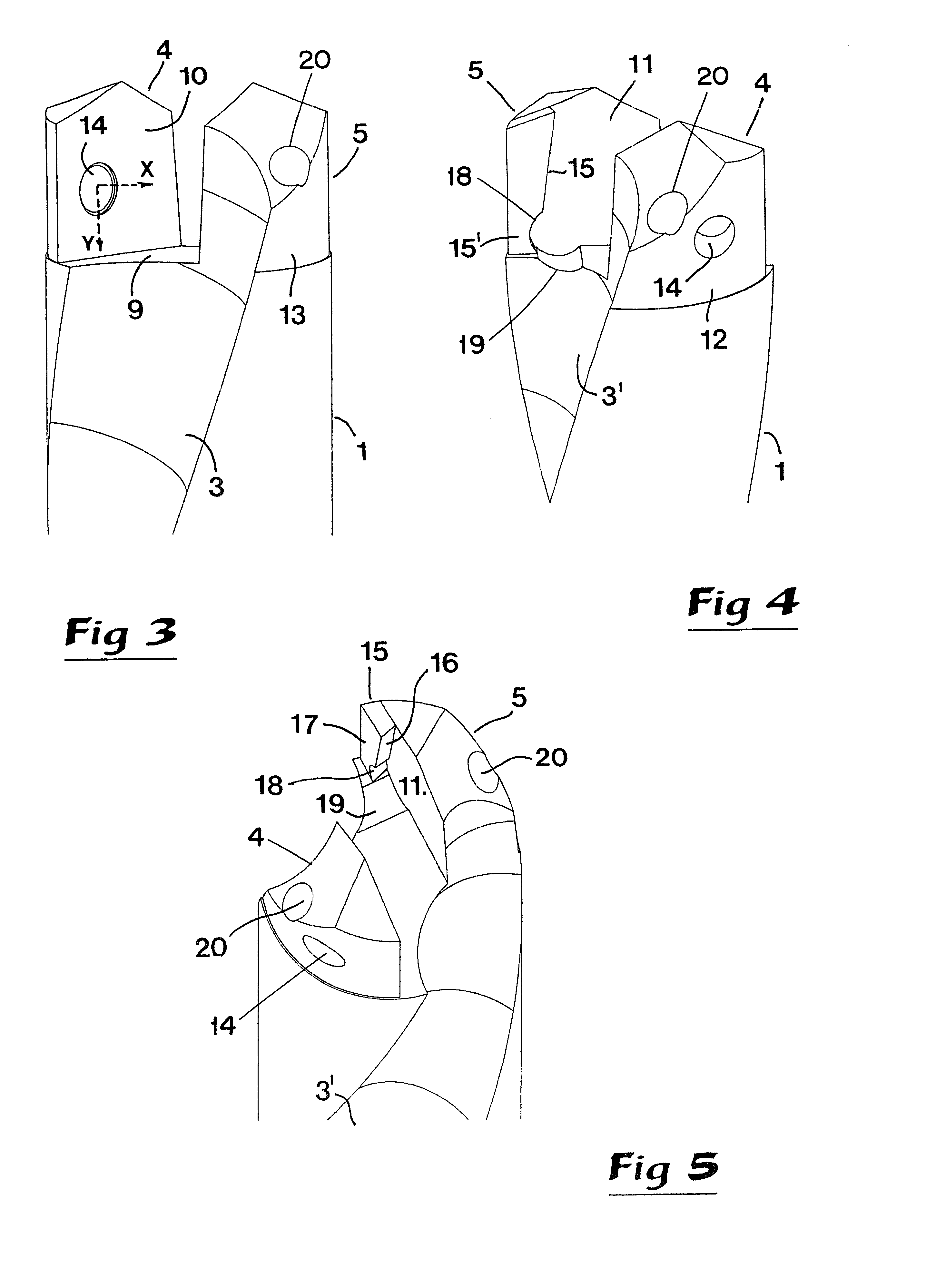
A front end of a drilling tool which includes a shaft 1 and a cutting body 2 is shown from opposite directions in FIGS. 1 and 2, respectively. In a conventional manner, the shaft 1 has an elongated cylindrical basic shape and two opposing chip channels 3, 3' extending helicoidally along the shaft in the rearward direction from the cutting body. The cutting body 2 is assembled on a seat formed in a front end of the shaft 1 which seat will be described in more detail with reference being made to FIGS. 3-5. Said seat, which by those skilled in the art is denominated a cutting seat, is delimited by two spaced-apart, axially projecting protrusions 4, 5 disposed on opposite sides of a center axis of the shaft. The front or axially outer portion (or top surface) of the cutting body 2 has one or more chip forming edges. In the example, the drill tool is assumed to be of a so-called DELTA-Hype, whereby two cutting edges 6, 6', illustrated schematically in FIGS. 1 and 2, extend at an obtuse a...


PUM

PropertyMeasurementUnit
angleaaaaaaaaaa
angleaaaaaaaaaa
angleaaaaaaaaaa

Abstract

A drilling tool includes a shaft having a front end to which a cutting body provided with cutting edges is detachably connected. In the front end of the shaft, a seat is formed which is delimited by spaced-apart protrusions between which there is a bottom surface. In the protrusion, there is a threaded hole for a screw, which when tightened applies pre-stressing forces to the cutting body. On the inside of the opposite protrusion, there is a supporting shoulder against which the cutting body is pressed when the screw is tightened and applies a lateral pre-stressing force to the cutting body. The protrusions are laterally displaced in relation to each other in order to freely expose the screw beside one of the protrusions.

Description

RELATED INVENTIONThis application claims priority under 35 U.S.C. .sctn..sctn.119 and / or 365 to patent application Ser. No. 0000883-9 filed in Sweden on Mar. 17, 2000; the entire content of which is hereby incorporated by reference.1. Technical Field of the InventionThis invention relates to a drilling tool of the type that comprises a shaft having a front end to which a cutting body provided with cutting edges is detachably connected by means of a screw.2. Prior ArtRecently, it has become common to manufacture not only drilling tools but also other types of chip forming tools, such as shaft-type cutters, thread cutters and the like, from two separate components, namely on the one hand, a shaft, which most often has a long narrow, cylindrical shape, and on the other hand a cutting body provided with cutting edges which can be detachably connected to a front end of the shaft. In modern machine tools, the tool shafts are so sophisticated and expensive that they, for economic reasons, ...

Claims


Application Information

Patent Timeline
Patent Type & Authority Patents(United States)
IPC IPC(8): B23B51/02B23B51/06B23B51/00B23C5/00B23C5/10
CPCB23B51/02B23B51/06B23B2251/02Y10T408/907Y10S408/713Y10T408/9097Y10T408/90993B23B2251/50
Inventor WIDIN, LEIF
Owner SANDVIK INTELLECTUAL PROPERTY AB
Why Eureka
Try Eureka