Column structures and methods for supporting compressive loads

a compression load and column structure technology, applied in the direction of buildings, buildings, constructions, etc., can solve the problems of column buckling, compression members are subject to some of the same failure modes as tension members, compression members become susceptible to unique failure modes,

Inactive Publication Date: 2002-11-26
DRAKE WILLIAM E
View PDF46 Cites 13 Cited by
  • Summary
  • Abstract
  • Description
  • Claims
  • Application Information

AI Technical Summary

Problems solved by technology

Compression members are subject to some of the same failure modes as tension members.
However, as the longitudinal length of the compression member increases relative to its cross-sectional dimension, the compression member becomes susceptible to a unique failure mode known as column buckling.
A column can buckle quickly and without warning, severely weakening and possibly destroying the structure of which it supports.
While effective, increasing the size of the column may result in a heavier and more costly member.
However, these alternatives may also result in more complicated, costly, and heavier structures.
However, such columns often require on-site fabrication which may include the forming of molds and the placement of reinforcing rods.
Thus, assembly time and expense may be significant.

Method used


Image

  • Column structures and methods for supporting compressive loads
  • Column structures and methods for supporting compressive loads
  • Column structures and methods for supporting compressive loads

Examples


Embodiment Construction

In the following detailed description of the embodiments, reference is made to the accompanying drawings which form a part hereof, and in which are shown by way of illustration specific embodiments in which the invention may be practiced. It is to be understood that other embodiments may be utilized and structural changes may be made without departing from the scope of the present invention.

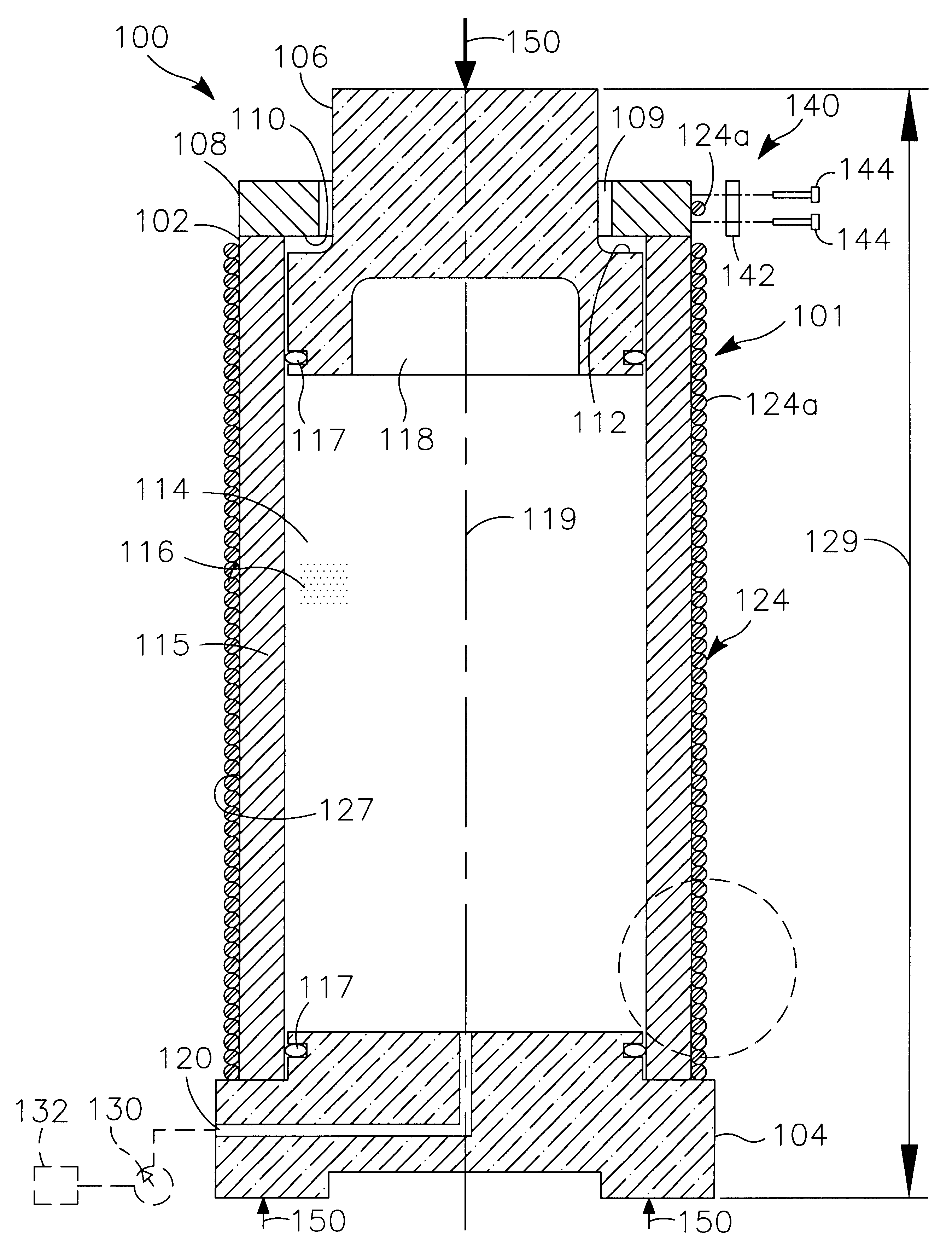
FIG. 1 illustrates a support member, e.g., column assembly 100, in accordance with one exemplary embodiment of the invention. The column assembly 100 preferably avoids or resists buckling failure by reacting the applied compressive loads as tangential, e.g., hoop, stresses in a wall 115 of the assembly 100. Tangential stresses, as known in the art, include stresses that act tangential to the wall 115 of the column assembly 100. By reacting the compressive loads in this manner, column assemblies in accordance with the present invention may substantially reduce the axial compressive stresses that t...


PUM


Abstract

A column assembly preferably includes a tube member having a wall that defines an interior volume. The column assembly is preferably operable to convert external, axial compressive forces applied to the column assembly into at least tangential stresses within the wall of the tube member. In one embodiment, an external compressive force causes increased pressurization of a filler material located within the volume of the tube member. The pressurized filler material produces tangential, tensile stresses within the wall of the tube member rather than axial compressive forces within the wall of the tube member. In some embodiments, a reinforcing, tension member, e.g., a wire rope, may be helically wound around the outer surface of the tube member along at least a portion of its longitudinal length.

Description

The present invention relates to load-supporting structures. More particularly, the present invention relates to columns and methods for supporting compressive loads via contained pressurization of a filler material within a column.Compression members are subject to some of the same failure modes as tension members. For example, members loaded in compression along their centroidal axis will deform until the elastic limit of the material is reached at which point they may plasticly deform or fracture.However, as the longitudinal length of the compression member increases relative to its cross-sectional dimension, the compression member becomes susceptible to a unique failure mode known as column buckling. Buckling is the result of various influences including material imperfections and variations, slight eccentricities or movements in the location of the compressive load, and other factors. While there is no clear point at which a compression member becomes subject to buckling failur...

Claims


Application Information

Patent Timeline
Patent Type & Authority Patents(United States)
IPC IPC(8): E04C3/30
CPCE04C3/30
Inventor DRAKE, WILLIAM E.
Owner DRAKE WILLIAM E
Why Eureka
Try Eureka