Multibeam electronic tube with magnetic field for correcting beam trajectory

a technology of electron tube and beam trajectory, applied in the direction of transit tube focussing arrangement, electric discharge tube, electrical apparatus, etc., can solve the problems of difficult to generate optimal magnetic focusing field, excessive interception entails not only prohibitive heating, complex and expensive cooling system, etc., and achieves the effect of not degrading the gain or efficiency characteristics

Inactive Publication Date: 2002-11-26
THOMSON TUBES ELECTRONIQUES
View PDF17 Cites 23 Cited by
  • Summary
  • Abstract
  • Description
  • Claims
  • Application Information

AI Technical Summary

Benefits of technology

The object of the present invention is therefore to reduce, or even cancel, this indu

Problems solved by technology

Compared with single-beam tubes, one of the main drawbacks is that it is difficult to generate an optimum magnetic focusing field which allows the beams to travel through the microwave structure without appreciable interception by the drift tubes.
Excessive interception entails not only prohibitive heating, which requires a complex and expensive cooling system, but also poor operation of the tube since expansion, degassing, frequency changes, oscillations, excitation of spurious modes, reflected electrons, ion bombardment and pertur

Method used


Image

  • Multibeam electronic tube with magnetic field for correcting beam trajectory
  • Multibeam electronic tube with magnetic field for correcting beam trajectory
  • Multibeam electronic tube with magnetic field for correcting beam trajectory

Examples


Embodiment Construction

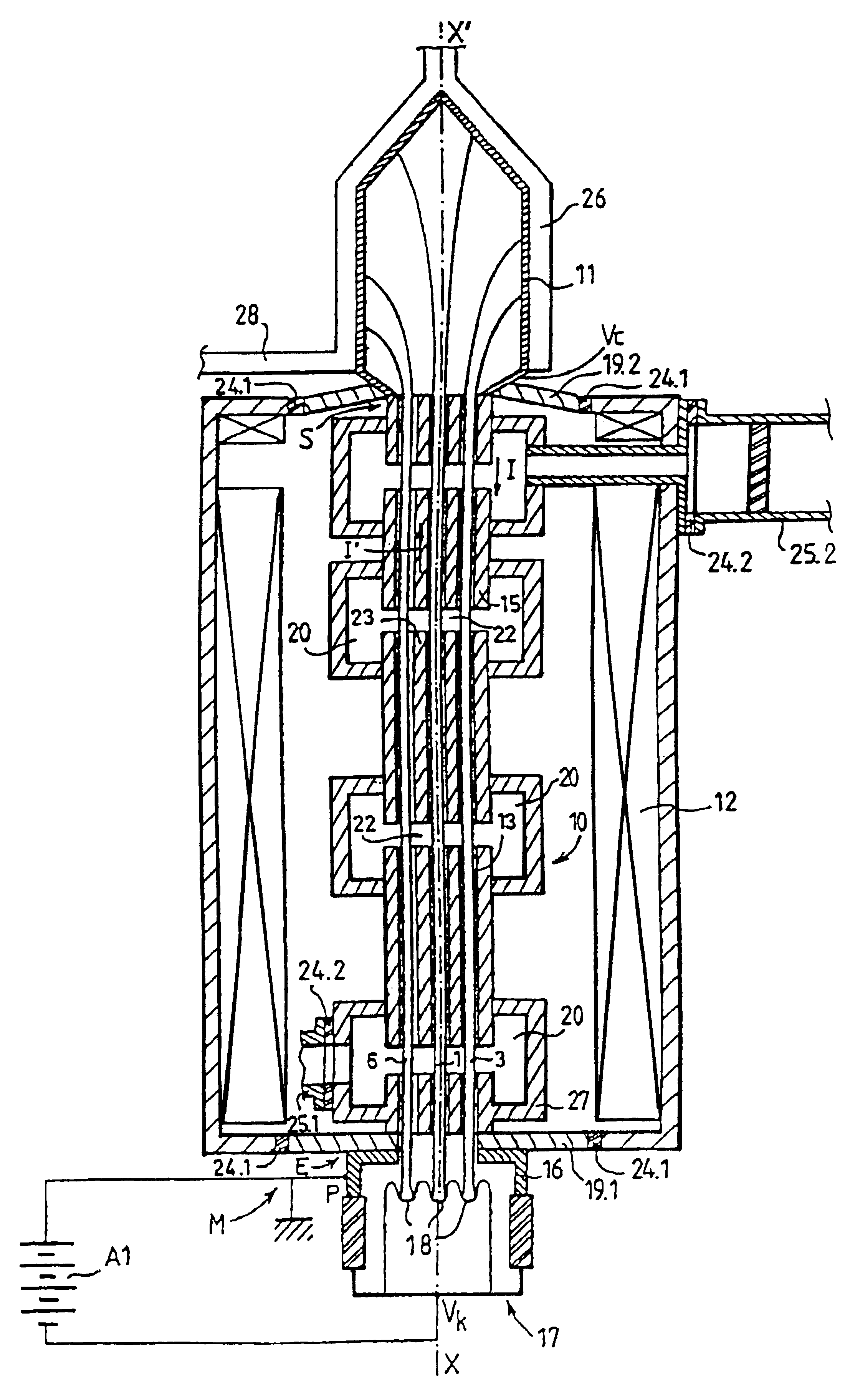
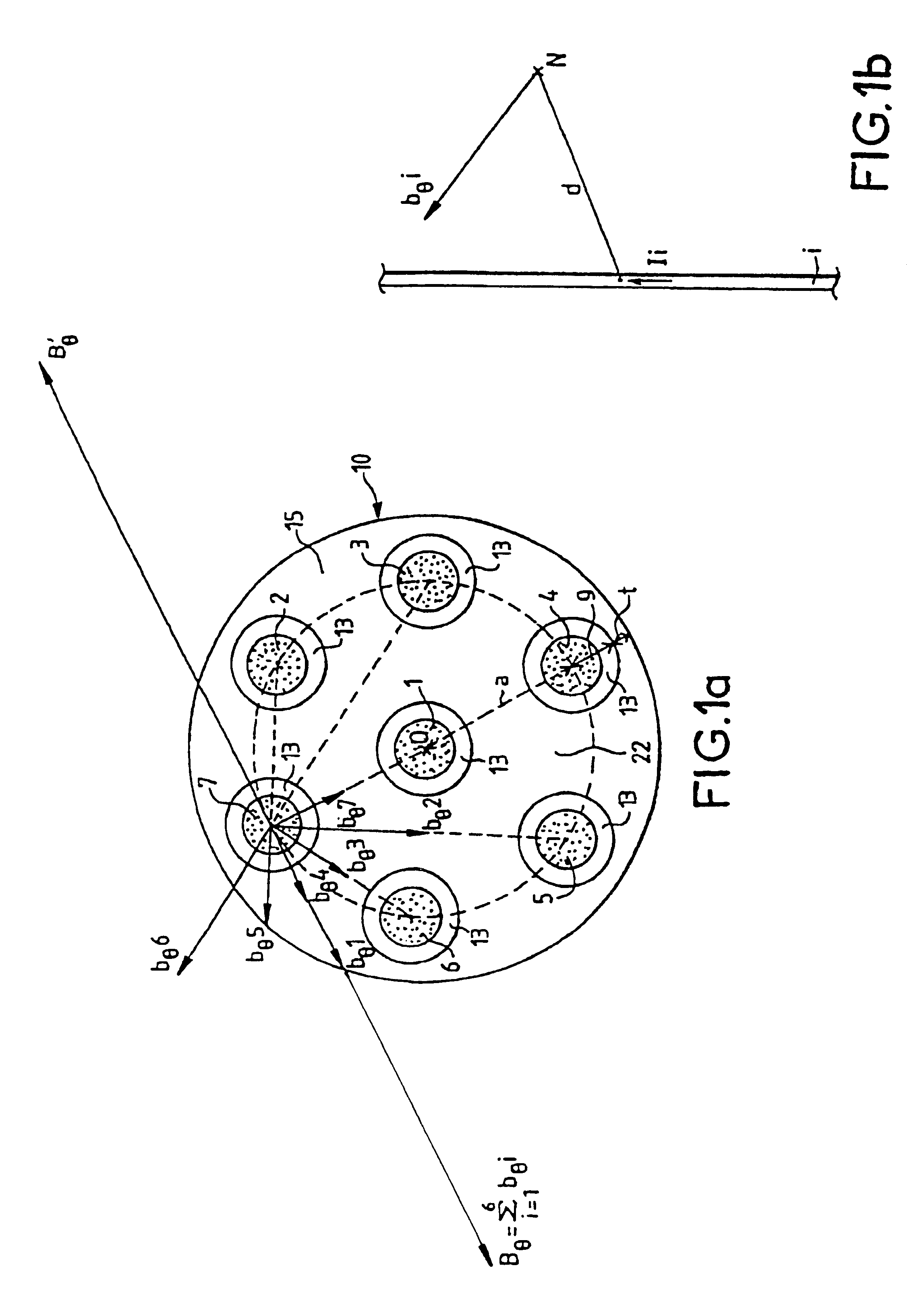
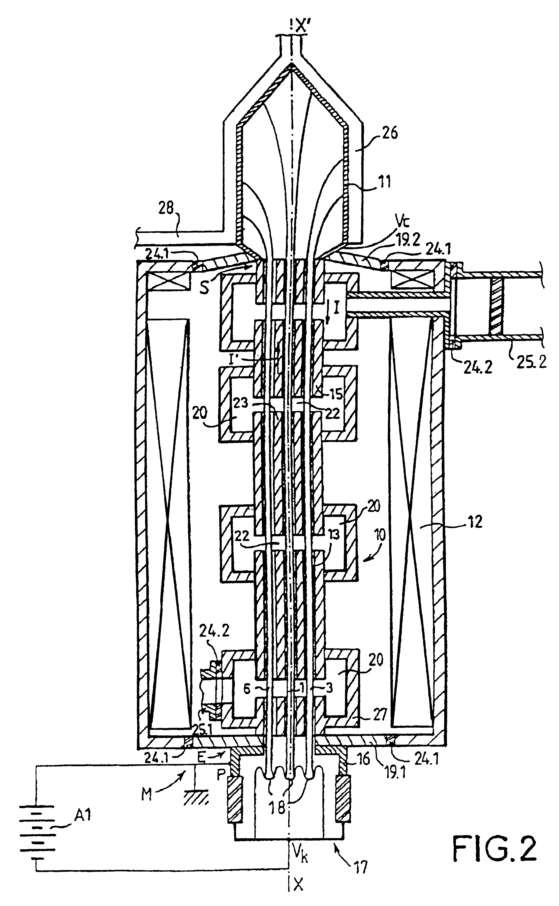
FIG. 1a shows, in cross section, the electron beams 1-7 of a multibeam tube. These approximately parallel beams are each contained in a drift tube 13 within the body. These drift tubes 13 are hollowed out in the same conducting block 15 which forms part of the body 10 of the tube. One of these beams 1 is centered on a central axis, perpendicular to the sheet, passing through the point 0. The other beams 2 to 7, arranged on a circle centered on 0, are off-axis. Conventionally, they are approximately equidistant from one another.

Referring to FIG. 1b, a beam i of current Ii creates, at a point N a distance d from the axis of the beam, in a plane perpendicular to the beam i, a magnetic field b.sub..theta. i approximately equal to:

where .mu..sub.0 is the magnetic permeability of the medium.

At least one off-axis beam 7 of the tube in FIG. 1a is therefore subjected, on the one hand, to its own field b.sub..theta. 7 which generates a nondeflecting centripetal focusing force and, on the othe...


PUM


Abstract

A multibeam electron tube with several approximately parallel electron beams passing through a body. Among the beams, at least some define an interbeam volume, each beam defining the interbeam volume being subjected to a perturbing azimuthal magnetic field induced by all the other beams. The tube includes an element allowing, in at least one conducting element located in the interbeam volume, flow of a reverse current in the opposite direction to that of the current of the beams, this reverse current generating, in the beams defining the interbeam space, a magnetic correction field whose purpose is to oppose the perturbing magnetic field. Exemplary embodiments of the present invention especially apply to the multibeam klystrons or traveling wave tubes.

Description

BACKGROUND OF THE INVENTION1. Field of the InventionThe present invention relates to multibeam longitudinal-interaction electron tubes such as, for example, klystrons or traveling wave tubes.2. Discussion of the BackgroundKlystrons, or traveling wave tubes, generally constructed about an axis, comprise several longitudinal electron beams parallel to this axis. These beams are often produced by a common electron gun, fitted with several cathodes, and are connected at the end of travel in one or more collectors. Between the gun and the collector, the beams pass through a body which is a microwave structure at the output of which microwave energy is extracted. This structure may be formed from a succession of resonant cavities and of drift tubes. The electron beams, in order to maintain their long thin shape, are focused by the magnetic field of a focuser which is centered on the main axis and surrounds the microwave structure.The advantages of multibeam electron tubes are the followin...

Claims


Application Information

Patent Timeline
IPC IPC(8): H01J23/09H01J23/02H01J25/02H01J23/087H01J25/34
CPCH01J23/09H01J2225/10H01J2225/36H01J25/06
Inventor BEUNAS, ARMELFAILLON, GEORGES
Owner THOMSON TUBES ELECTRONIQUES
Why Eureka
Try Eureka