Car antenna

a technology for antennas and cars, applied in the direction of antennas, antenna details, antenna adaptation in movable bodies, etc., can solve the problem of large number of workers needed for mounting operation, and achieve the effect of sufficient strength and smooth insertion

Inactive Publication Date: 2002-11-26
HARADA IND CO LTD
View PDF10 Cites 40 Cited by
  • Summary
  • Abstract
  • Description
  • Claims
  • Application Information

AI Technical Summary

Benefits of technology

Also, the fixing plate, which is formed to have a U-shaped cross section, is fixed by inserting the opposite side plates whereon are formed spring portions so as to incline outwards into the hole portion formed in the base portion; as a result, the fixing plate can be fixed with sufficient strength to the base portion. In this case, the board bracket formed as a single piece with the fixing plate is attached to the base portion, the fixing plate is held by the base portion and board bracket, and the board bracket is attached to the base portion thereby.
Furthermore, part of the side surface of the cylindrical projecting portion along the side plates of the fixing plate is cut away so that the surfaces of the side plates of the fixing plate do not project outside of the side surface of the cylindrical projecting portion. As a result, when the cylindrical projecting portion formed on the base portion is inserted in the mounting hole formed in the vehicle body, the cylindrical projecting portion can be smoothly inserted in the mounting hole, without the fixing plate located on the side surface of the cylindrical projecting portion striking the edge portion of the mounting hole.

Problems solved by technology

In this way, two workers, inside and outside the vehicle body, are needed to mount a conventional automobile antenna, and thus such conventional automobile has a problem that the large number of workers needed for the mounting operation.

Method used


Image

  • Car antenna
  • Car antenna
  • Car antenna

Examples


Embodiment Construction

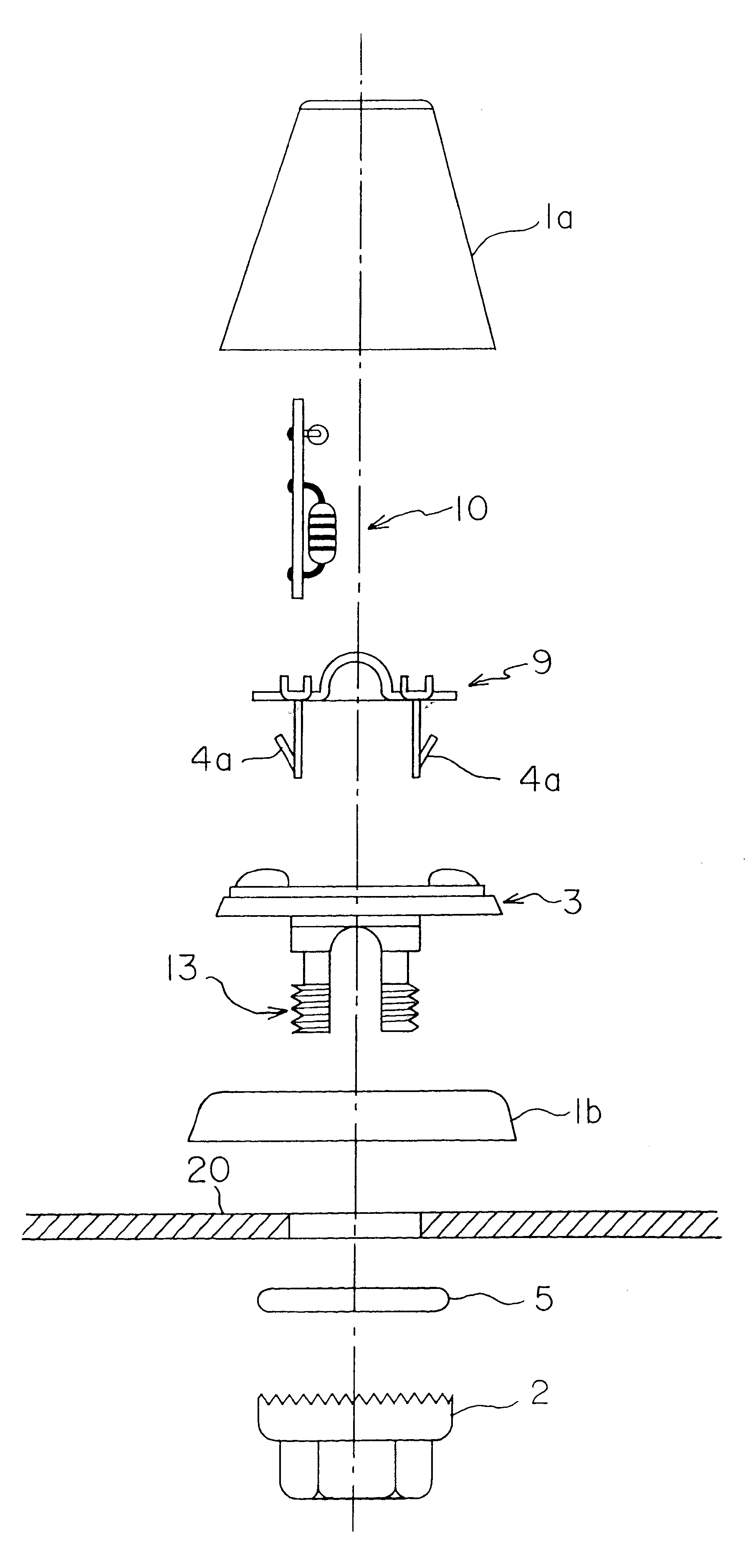
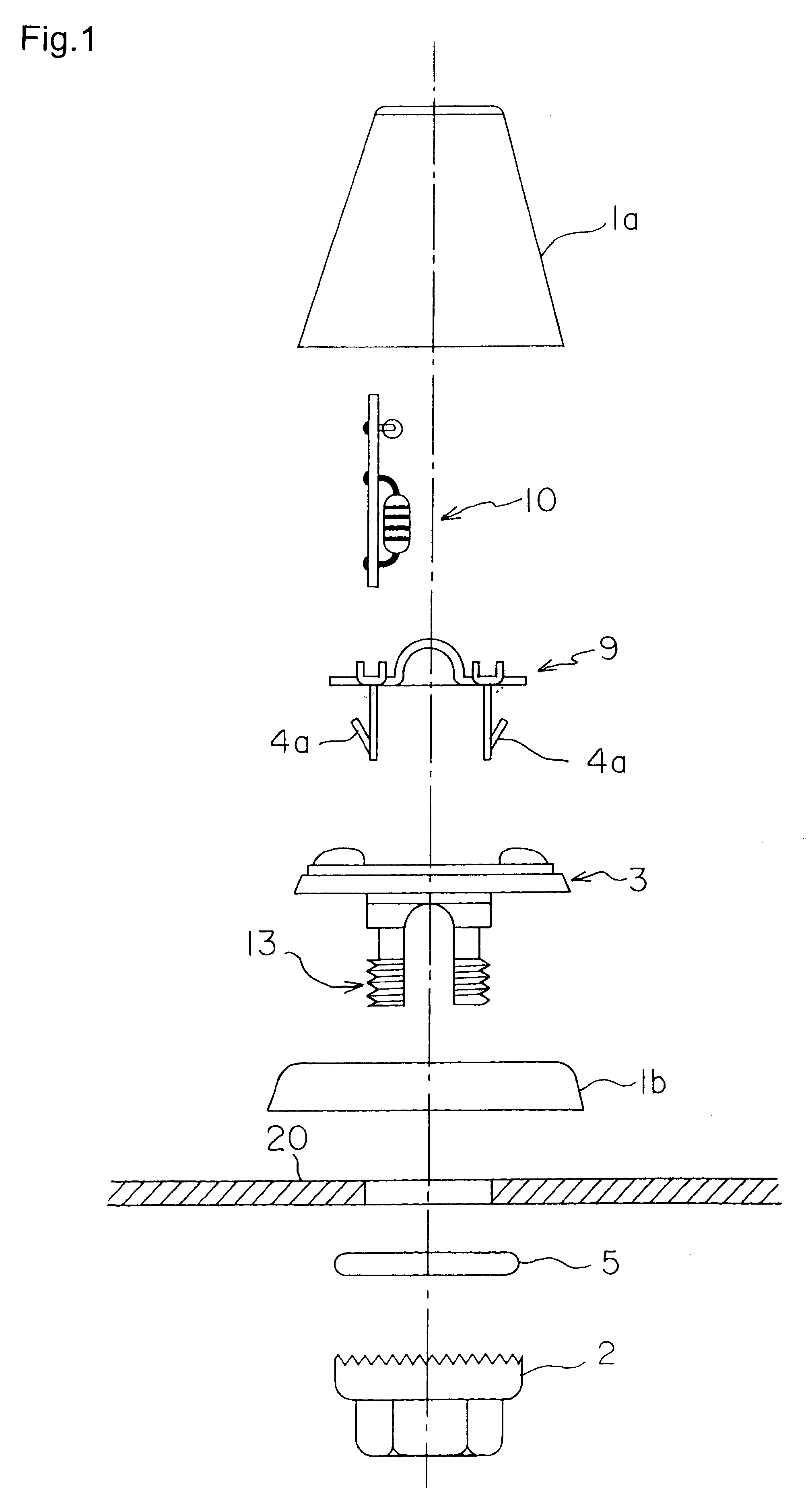
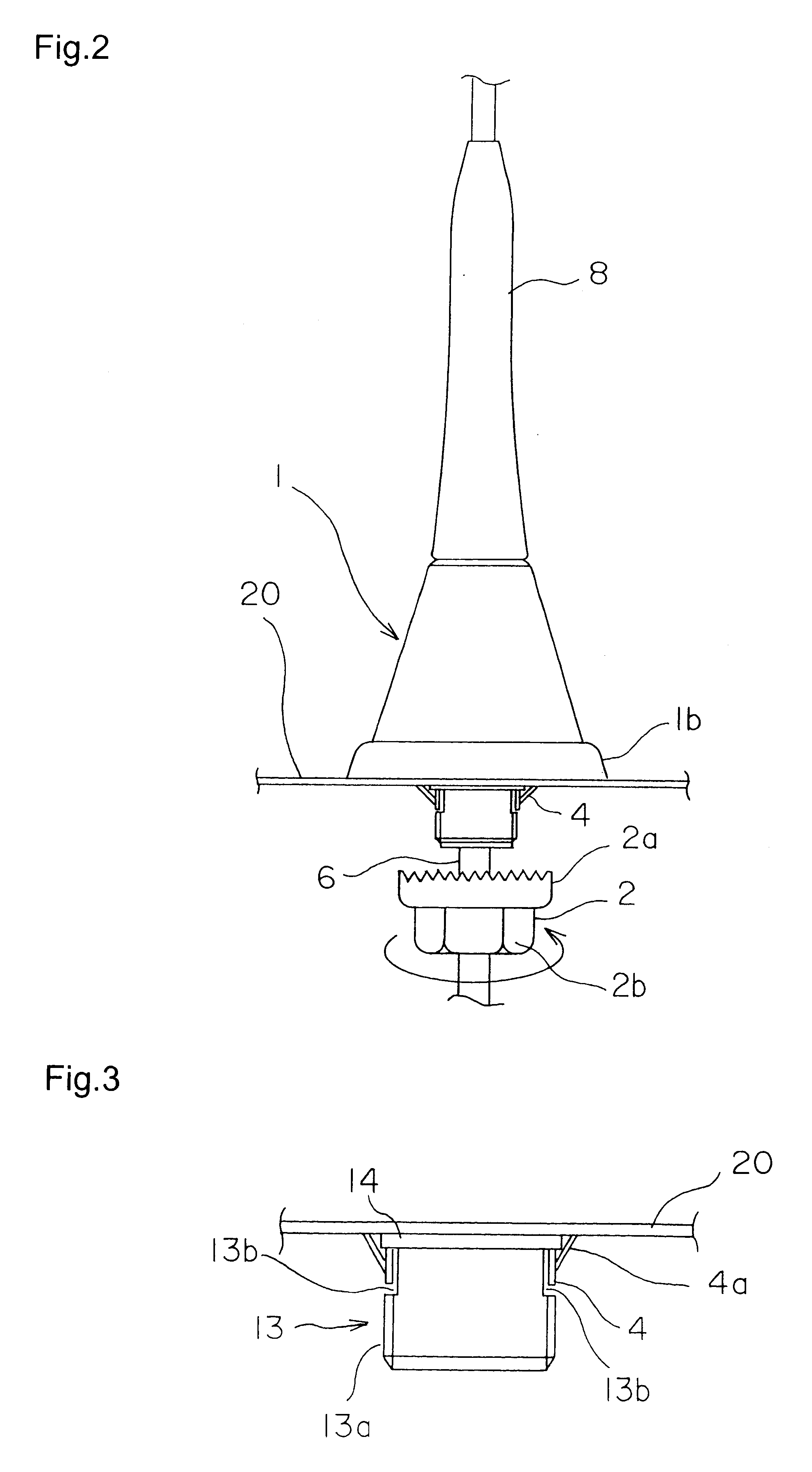
FIGS. 1 through 3 show examples of the constitution of an embodiment of the automobile antenna relating to the present invention.

FIG. 1 is an exploded view showing the constitution of an embodiment of the automobile antenna relating to the present invention; FIG. 2 is a front view showing the constitution of an embodiment of the automobile antenna relating to the present invention; and FIG. 3 is an enlarged view showing a detail of principal elements located on the lower portion of the vehicle body in an embodiment of the automobile antenna relating to the present invention.

As shown in these figures, the automobile antenna relating to the present invention comprises an antenna body 1 and a fixing nut 2 for attaching the antenna body 1 on the vehicle body. The antenna body 1 comprises an element portion 8 and an antenna cover 1a to which the element portion 8 is fixed. An antenna top with a diameter greater than that of the element portion 8 is attached to the top end of the element ...


PUM


Abstract

With the object of a single worker being able to mount an automobile antenna, side plates of a board bracket 9 with fixing plate are inserted into a rectangular hole formed in the base portion 3 so that [the side plates] are located on the opposite side surfaces of a rectangular projecting portion projecting from the bottom surface of the base portion 3. Spring pieces 4a are formed on these side plates. When the cylindrical projecting portion 13 extending from the rectangular projecting portion is inserted in the mounting hole formed in the roof panel, the spring pieces 4a formed on the side plates pass through the mounting hole and engage with the back side thereof. The antenna body is thereby temporarily fixed to the roof panel and a worker can remove his or her hands from the antenna body. The worker then goes within the vehicle body, screws the fixing nut 2 onto the cylindrical projecting portion 13, and can thereby fix the automobile antenna on the roof panel.

Description

TECHNICAL FIELDThe present invention relates to an automobile antenna whose antenna body, comprising an antenna element, is attached to the vehicle body.BACKGROUND ARTThis type of automobile antenna is generally mounted on the roof panel 20 of the automobile as shown in FIG. 10.The antenna body 1 of this automobile antenna comprises an antenna cover 1a and an element portion 8 attached to the antenna cover 1a; a base portion, not shown, is fixed to the lower end of the antenna cover 1a. As shown in FIG. 11a, a cylindrical projecting portion 13 is formed on the lower surface of this base portion so as to project therefrom. The antenna body 1 is fixed to the roof panel 20 by screwing a fixing nut 2 onto this cylindrical projecting portion 13. In this case, the base portion of the cylindrical projecting portion 13 is a rectangular projecting portion. A rectangular antenna mounting hole 21 is formed in the roof panel 20, as shown in FIG. 11b, such that the rectangular projecting portion...

Claims


Application Information

Patent Timeline
Patent Type & Authority Patents(United States)
IPC IPC(8): H01Q1/12H01Q1/32H01Q1/22
CPCH01Q1/1214H01Q1/3275H01Q1/32
Inventor IMAHIGASHI, HIROTSUGU
Owner HARADA IND CO LTD
Why Eureka
Try Eureka