
Packet data switching apparatus

a data switching and data technology, applied in data switching networks, time-division multiplexing selection, instruments, etc., can solve the problems of time-consuming searching, system implementation, and complex implementation of systems

Inactive Publication Date: 2002-12-03
TELEFON AB LM ERICSSON (PUBL)
View PDF20 Cites 7 Cited by
  • Summary
  • Abstract
  • Description
  • Claims
  • Application Information

AI Technical Summary

Problems solved by technology

Such a system, however, can be very complex to implement.
Such searching can, however, be time-consuming.

Method used


Image

  • Packet data switching apparatus
  • Packet data switching apparatus
  • Packet data switching apparatus

Examples


Embodiment Construction

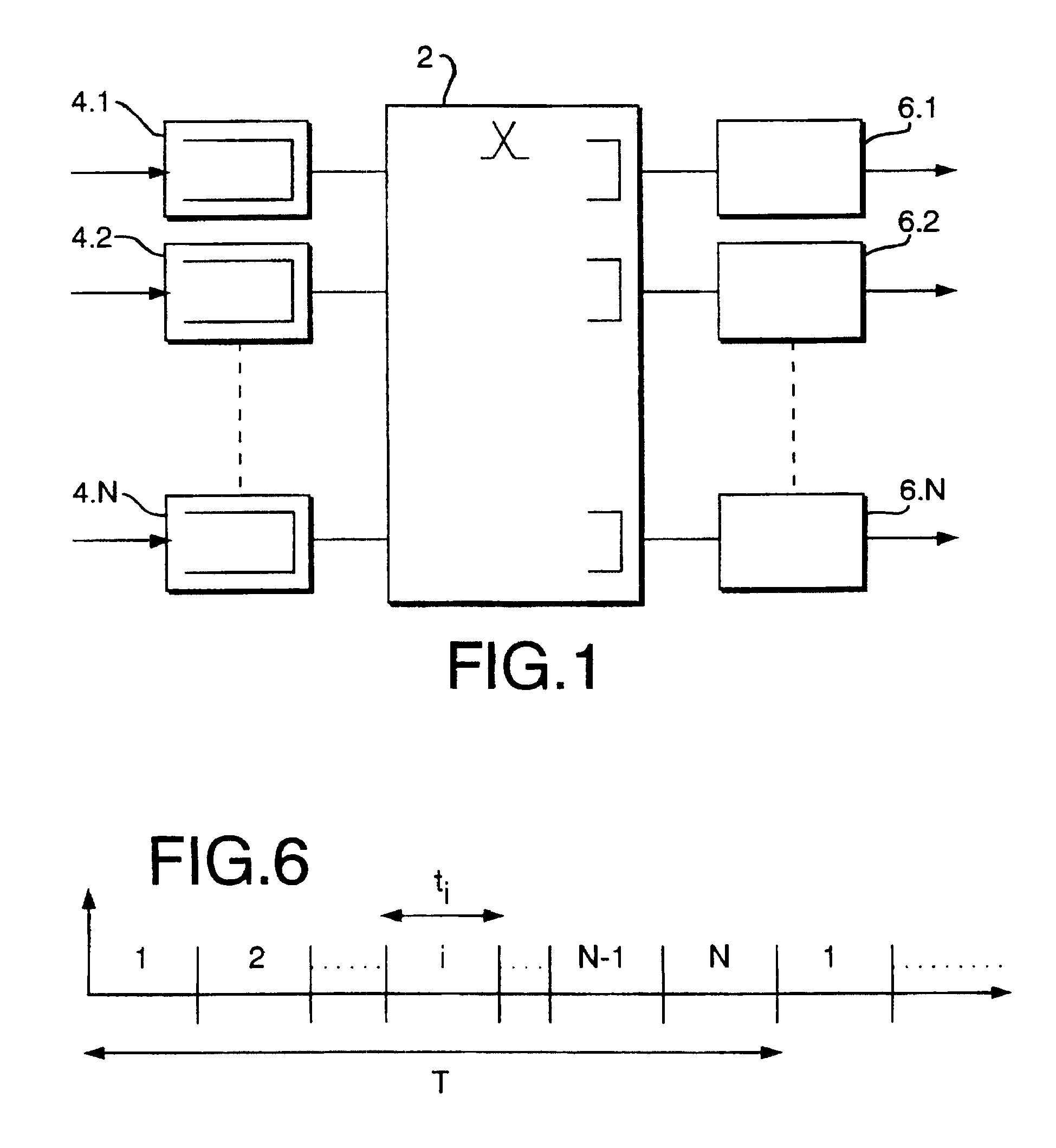
FIG. 1 shows a switch of the type to which the present invention relates. A switching device 2 has N input ports 4.1, 4.2, . . . , 4.N, each with an associated input buffer. Similarly, the switch 2 has N output ports 6.1, 6.2, . . . , 6.N, each with an associated output buffer. Each input buffer can be thought of as being divided into N logical buffers, each associated with a respective one of the output ports, so that input cells received at a particular input port are stored in that input port's input buffer associated with the output port for which the cell is intended. However, in practice, the different logical buffers at each input port share a single input buffer associated with the input port, to increase buffer utilisation.

The present invention is concerned with improving the fairness of the way in which the output capacity of each output port is shared between the different input ports. Thus, it is desired to avoid a situation whereby a single connection, generating a larg...


PUM


Abstract

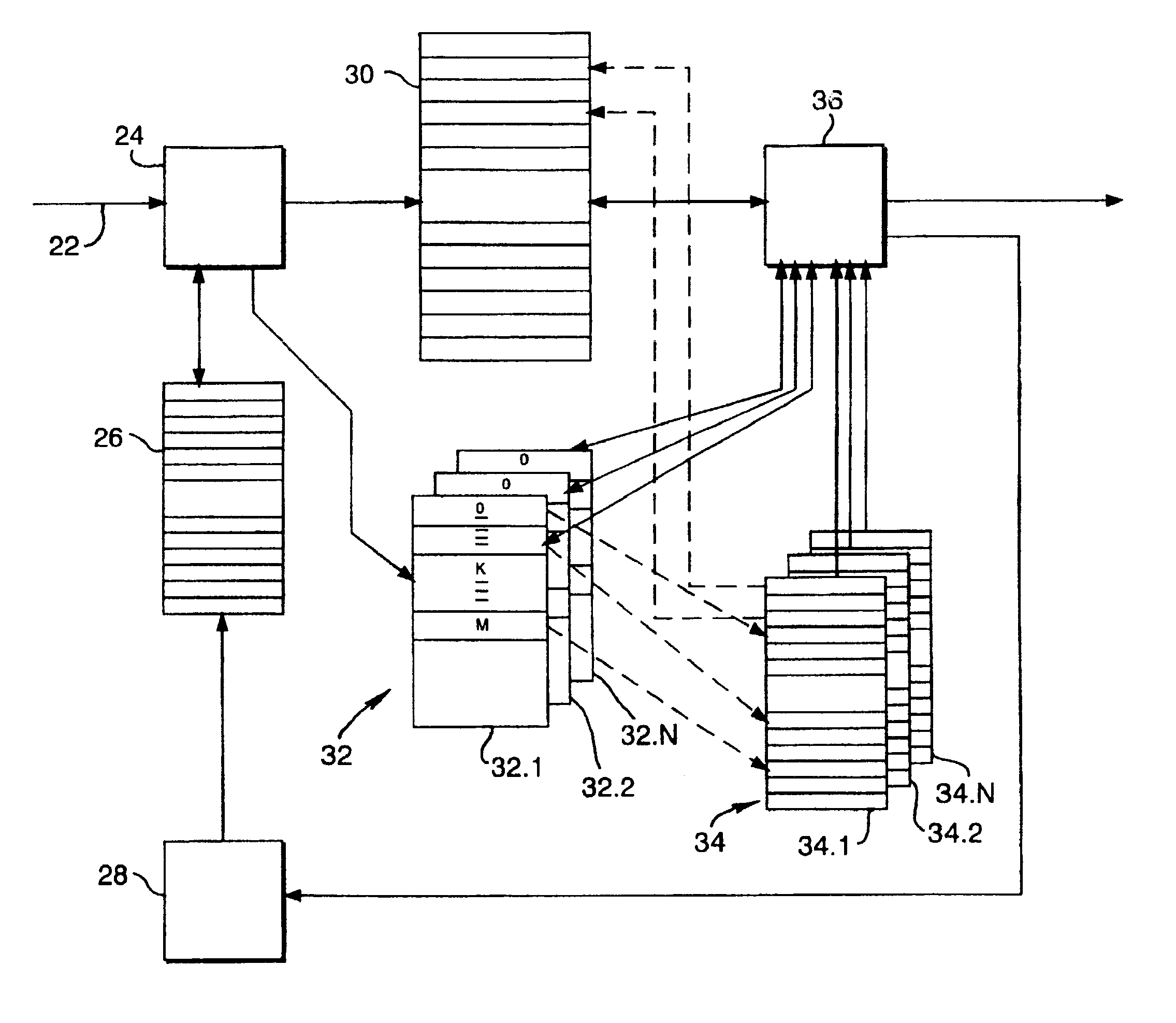
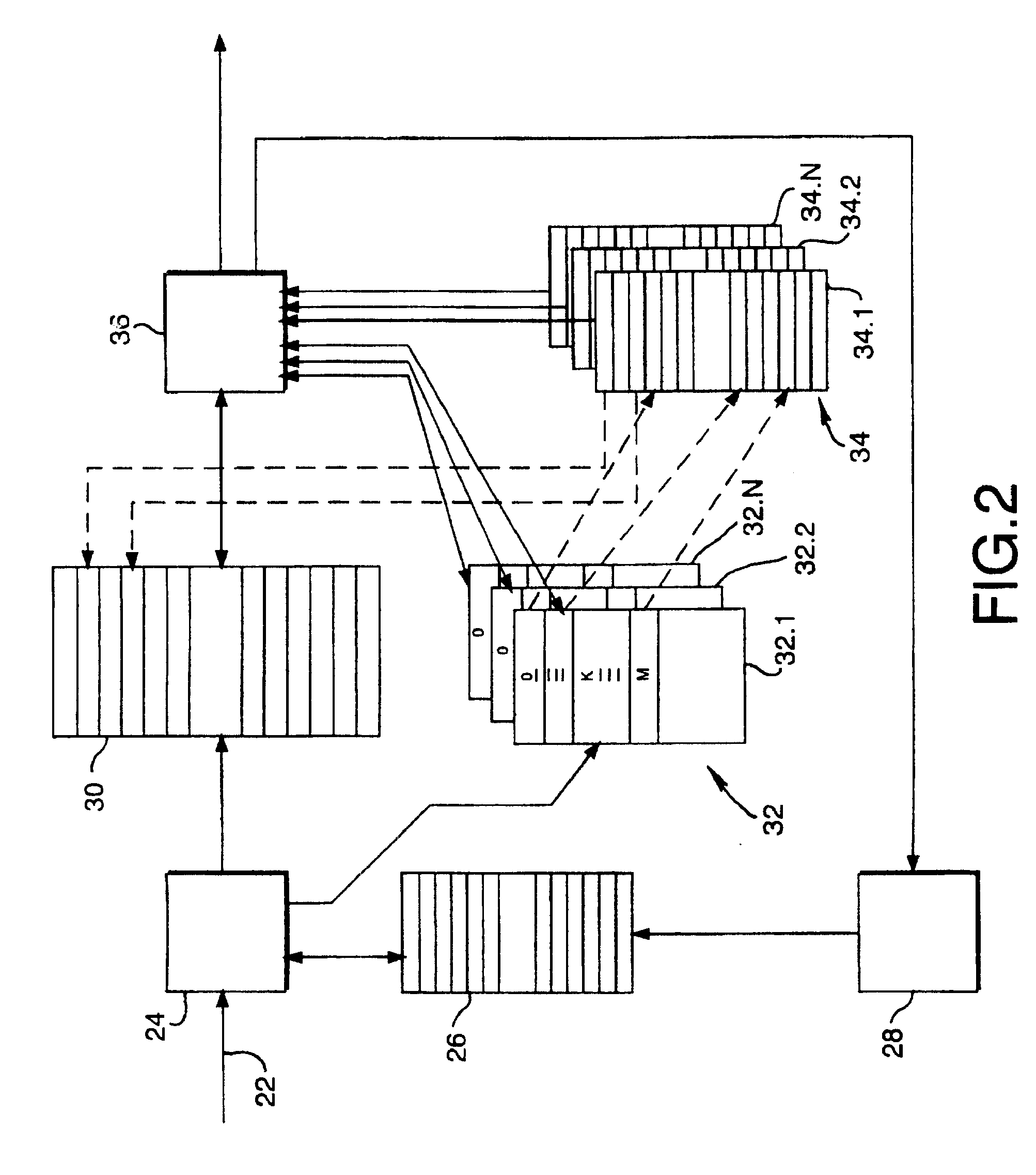
There is disclosed a packet data switch which allows fair queuing, by assigning a priority value to received data, without requiring time-consuming searches, by storing pointers to the buffer memory in a first memory, and accessing the pointers through a second memory which is in the form of an array, addressable by the priority value. There is further disclosed a system which combines fair queuing and FIFO queuing, to avoid the need for excessive array size.

Description

This invention relates to a switching device, and in particular to an ATM switching device which exhibits fairness in the way in which it handles incoming traffic at different inputs.DESCRIPTION OF RELATED ARTOne proposed solution to the problem of allocating network resources to the users of an integrated services network for packet-based traffic is known as Weighted Fair Queuing, in which arriving data packets are reordered so that they are retransmitted with a degree of fairness in the processor sharing system. See, for example, Parekh & Gallagher "A Generalized Processor Sharing Approach to Flow Control in Integrated Services Networks: The Single-Node Case" IEEE / ACM Transactions on Networking, Vol. 1, No. 3, June 1993. Such a system, however, can be very complex to implement.U.S. Pat. No. 5,455,825 discloses a switch for digital communications networks, including a queuing system. When incoming cells or packets arrive, they are provided with numerical tags, calculated in accorda...

Claims


Application Information

Patent Timeline
Patent Type & Authority Patents(United States)
IPC IPC(8): H04L12/56H04Q11/04H04L49/111
CPCH04L49/30H04L49/3018H04L49/3081H04Q11/0478H04L49/20H04L49/50H04L2012/5651H04L2012/5681
Inventor JOHANSSON, PER
Owner TELEFON AB LM ERICSSON (PUBL)
Learn More