

Physical restraining pad assembly and system
a technology of restraining pads and restraining pads, which is applied in the field of physical restraining pads, can solve the problems of physical restraint, injury to the attendant, and difficulty in ensuring the safety of the attendant, so as to promote the flexibility of the first, maintain and promote the effect of breathability
Inactive Publication Date: 2002-12-10
MCQUEEN ANGUS A
View PDF6 Cites 6 Cited by
- Summary
- Abstract
- Description
- Claims
- Application Information
AI Technical Summary
Benefits of technology
It is another object of the invention to provide a physical restraining pad assembly that is easy to use in order to restrain an individual.
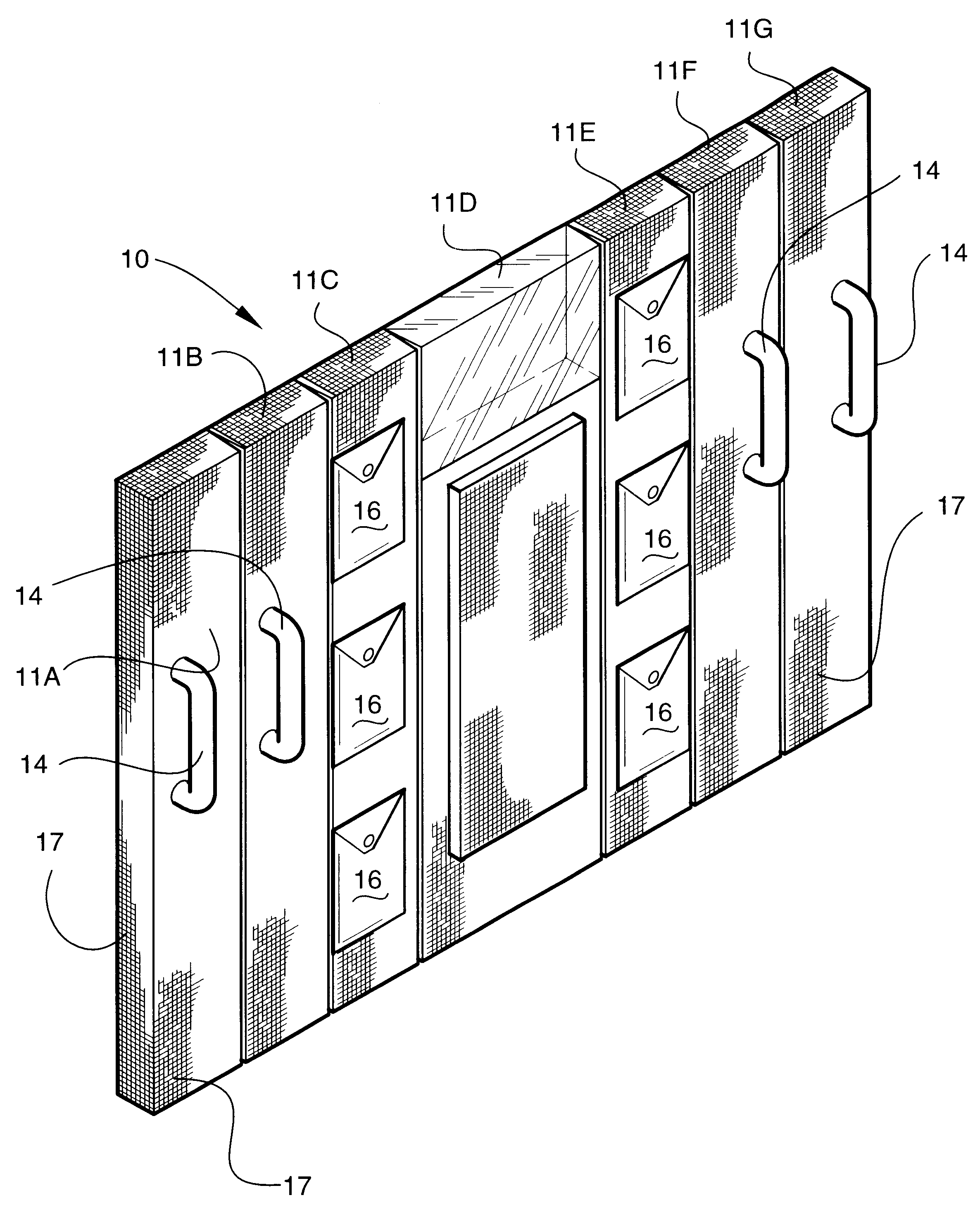
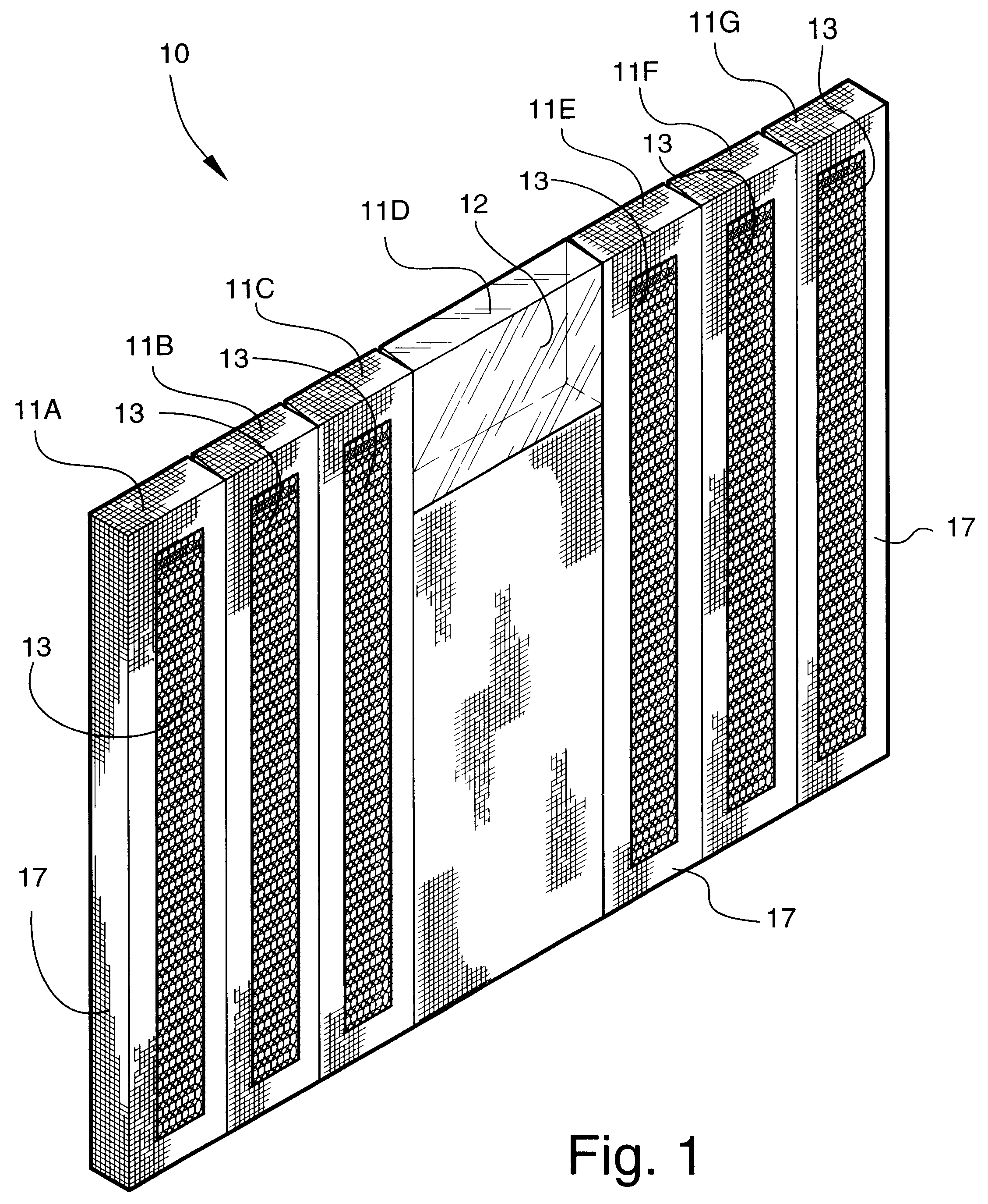
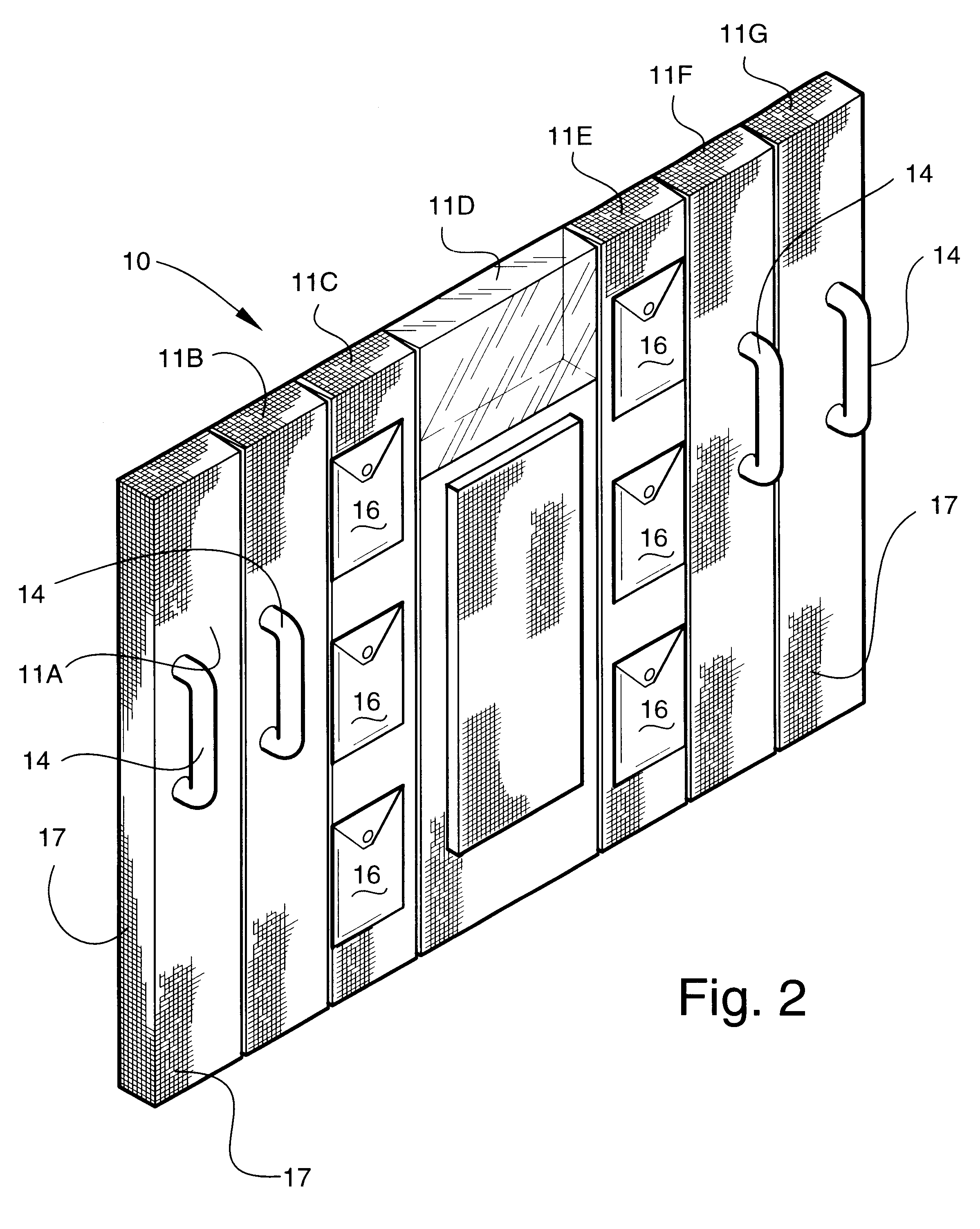
Additional resistance to peeling separation, particularly in a diagonal direction, can be achieved by providing supplemental loop strips positioned in a diagonal direction. Segments 39A-44A are attached to the surface of the pad assembly 30, while segments 39B-45B are loose and function as described above. An attempt to separate the pad assemblies 20 and 30 by moving one horizontally or vertically relative to the other one would cause the loose segments 39B-45B in the direction opposite the direction of movement to lift away from the surface of the pad assembly 30, thus preventing the shearing action necessary to separate the loops and hooks.
Problems solved by technology
Because physical restraint is usually required under less than ideal circumstances involving either or both an agitated, violent individual and one or more cautious yet apprehensive attendants, problems may arise when restraint is attempted.
One such problem is injury to the attendant due to uncontrolled, violent and forceful movements of the individual being restrained.
Also, once an individual is restrained, escape is a concern.
Finally, because of the volatile circumstances giving rise to the need to physically restrain an individual, restraint attempts may be unsuccessful.
Method used
View moreImage
Smart ImageViewing Examples

Examples
example
For use in restraining an adult, the pad assemblies 10, 20 or 30 will be approximately 5' in height and 6' in width with a thickness of 21 / 2". Alternately, for use in restraining a child or small adult, the pad assemblies 10, 20 or 30 will be approximately 2' in height and 3' in width with a thickness of 21 / 2'.
Login to View More PUM
 Abstract
A physical restraining pad assembly including a pad constructed of a flexible, breathable material of a size and shape to cover the body of an individual with arms outstretched. An outer mesh covering encloses the pad. A plurality of spaced handles are positioned on a back side of the pad for use by an attendant. The pad has a viewing window of a size and shape to allow the attendant to see through the pad for observing the individual being restrained. Complementary touch fasteners on a pair of such pads may be used by two attendants to restrain an individual between them. A single pad with complementary touch fasteners on opposing sides may be used to restrain an individual by wrapping the individual within the pad with the complementary touch fasteners engaged with each other.
Description
TECHNICAL FIELD AND BACKGROUND OF THE INVENTIONThis invention relates to a physical restraining pad assembly and system. It is often necessary to employ a physical restraint device to restrain an individual who becomes violent for one reason or another to prevent that individual from hurting himself or others. Physical restraint systems are commonly practiced in prisons, mental institutions, and other facilities as well as in public, i.e., to effect arrests or involuntary immobilizations. Because physical restraint is usually required under less than ideal circumstances involving either or both an agitated, violent individual and one or more cautious yet apprehensive attendants, problems may arise when restraint is attempted. One such problem is injury to the attendant due to uncontrolled, violent and forceful movements of the individual being restrained. This invention provides protection to attendants through padding and, optionally, impact-resistant kick protection panels. This i...
Claims
Login to View More Application Information
Patent Timeline
 Patent Type & AuthorityPatents(United States)
IPC IPC(8): A61F5/37
CPCA61F5/37
InventorMCQUEEN, ANGUS A.
OwnerMCQUEEN ANGUS A