Snowmobile with pivotable rear snow flap

a rear suspension system and snowmobile technology, applied in road vehicles, superstructure sub-units, transportation and packaging, etc., can solve the problems of limiting the range of "travel" of the rear suspension system, and affecting the safety of the vehicl

Inactive Publication Date: 2002-12-10
BOMBARDIER RECREATIONAL PROD INC
View PDF24 Cites 42 Cited by
  • Summary
  • Abstract
  • Description
  • Claims
  • Application Information

AI Technical Summary

Benefits of technology

In one aspect, the invention features a snowmobile in which the chassis is shorter than in conventional snowmobiles and does not extend over the entire track. Rather, the track extends longitudinally rearwardly beyond the rear end of the chassis. This reduces the weight of the snowmobile and hence, because the length of the chassis is reduced, the polar moment of inertia of the snowmobile. This reduction in weight and polar moment of inertia improves maneuverability and overall performance of the snowmobile.
Because the end of the chassis does not shield the track system from spraying snow up and / or rearwardly, a pivotal snow flap is provided above and extending beyond the rear portion of the track to prevent or substantially reduce the amount of snow sprayed by the tread as the snowmobile moves through the snow. The snow flap is pivotally connected at its forward end to the rear end of the chassis and is caused to pivot by virtue of its connection to the track system by means of linkage struts. The linkage struts are pivotally connected to a portion of the snow flap and to the track system. This arrangement causes the snow flap to pivot relative to the chassis as the track system moves through its range of travel and keeps the track shielded. Additionally, because the snow flap moves with the rear suspension travel, the tread will not contact the snow flap and / or the chassis, and hence will not abrade and degrade those components.
In another aspect, the invention features a handle-shaped bumper that is connected to the snow flap. Because the snow flap is connected to the track system, it is easier to lift the rear of the snowmobile when necessary to do so, e.g., when lifting the snowmobile out of a small gully. This is because the lifting action acts virtually directly on the track system via the bumper (which is connected to it), whereas in the prior art, it was customary to lift through a bumper mounted at the rear of the chassis and a certain degree of lifting motion was lost as the chassis rose relative to the track system (as the "play" in the suspension system was being taken up) before the tread ever began to be lifted from the ground. Additionally, lifting the rear end of the snowmobile according to the invention is easier with the bumper connected to the snow flap than the case where the bumper extends from the rear of the chassis because the lower position requires a person lifting the rear of the snowmobile to bend from the knees to reach it, whereas the prior art arrangements only required the person to bend from the waist to reach the bumper, and it is easier to lift "with the legs" than "with the back."

Problems solved by technology

Shortening the chassis, however, exposes part of the rear portion of the track and leaves that rear portion uncovered, which may result in greater amounts of snow being splashed or sprayed upwardly and / or rearwardly than is desired.
Furthermore, when the entirety of the track system is positioned under the chassis, as in conventional snowmobiles, the chassis limits the range of "travel" of the rear suspension system.
In particular, it has been observed that as a conventional snowmobile moves over uneven terrain, as the track system moves to the upper limit of the range of travel or the rear suspension system, the rotating track may strike the undersurface of the chassis.

Method used


Image

  • Snowmobile with pivotable rear snow flap
  • Snowmobile with pivotable rear snow flap
  • Snowmobile with pivotable rear snow flap

Examples


Embodiment Construction

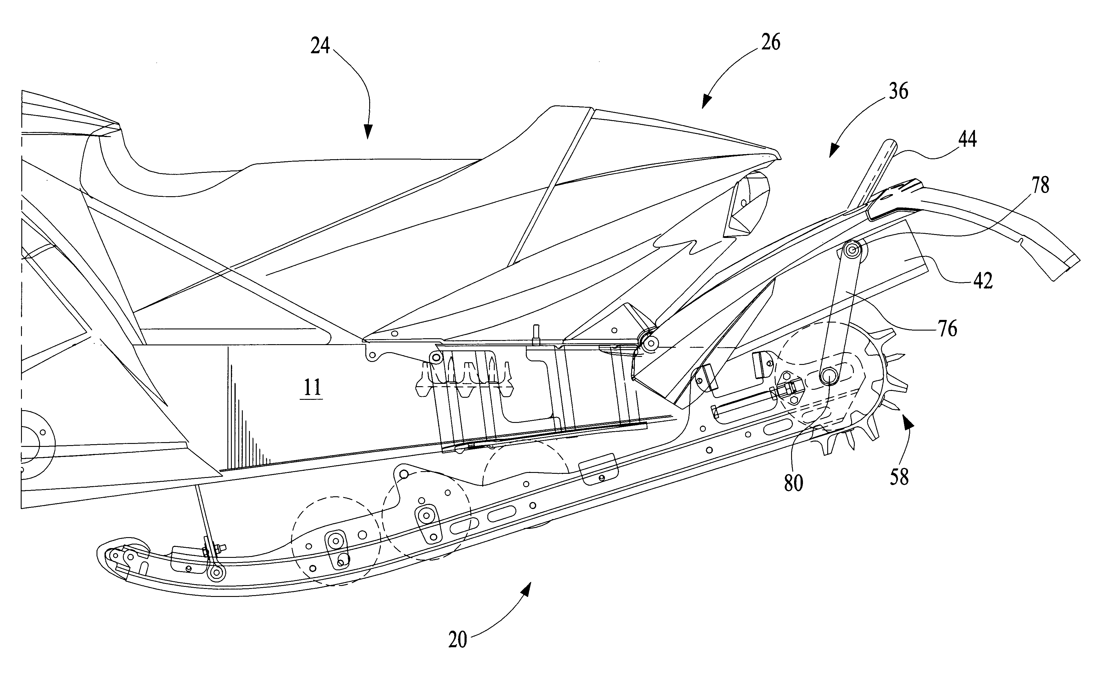
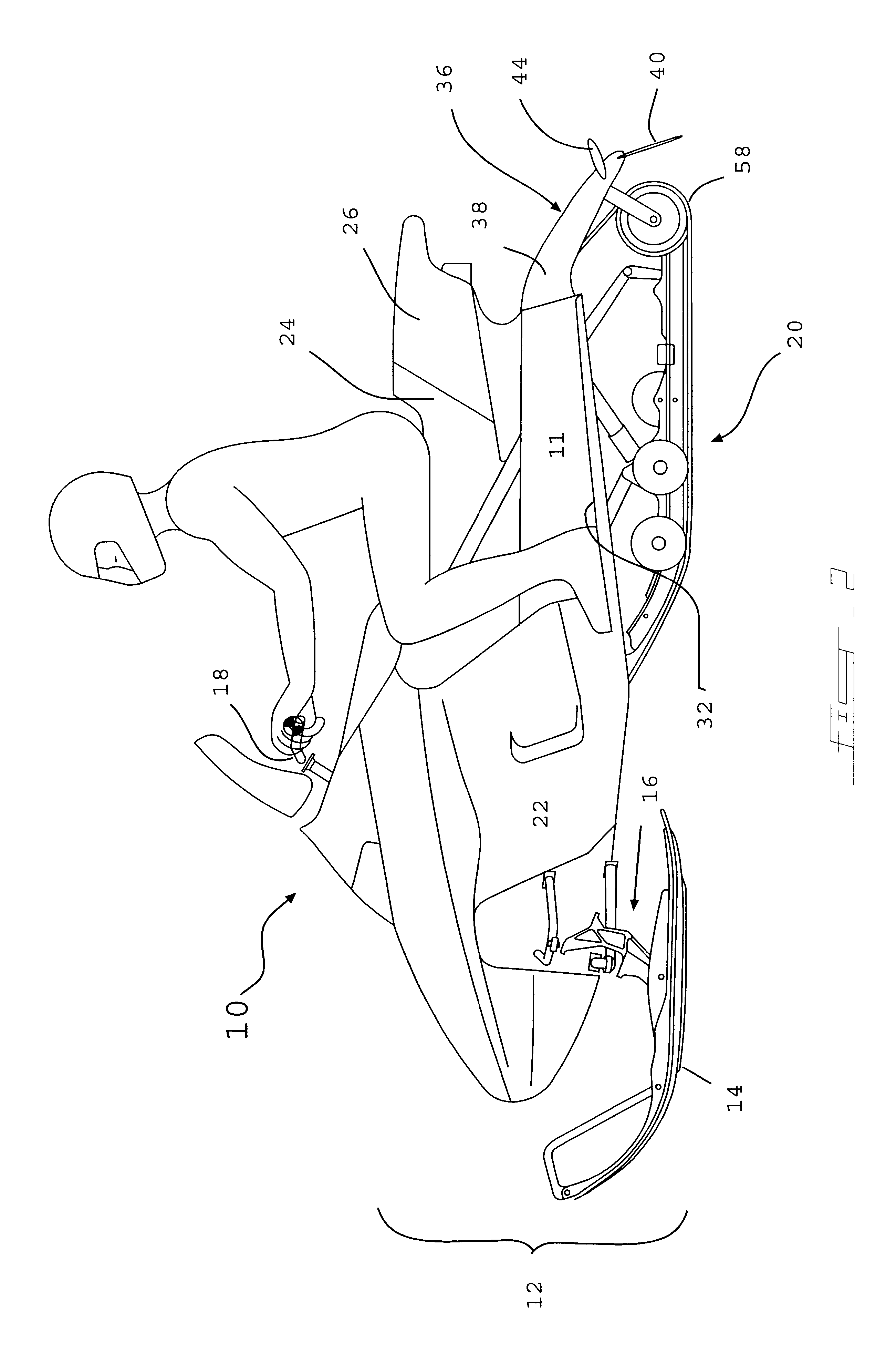
The overall configuration of a snowmobile 10 according to the invention is shown in FIGS. 2-6. In general, the snowmobile 10 includes an aluminum chassis 11 around which the various snowmobile components are assembled. The snowmobile has a front suspension system 12 located at a forward portion of the chassis to support the forward portion of the snowmobile 10 on the ground. The front suspension 12 includes a pair of skis 14 which are positioned at the laterally outermost end portions of suspension arms 16, which suspension arms have, e.g., shock absorbing struts to absorb vibrations as the snowmobile 10 passes over uneven terrain. The skis 14 and the suspension arms 16 are constructed so that the skis 14 can be pivoted laterally to steer the snowmobile 10, e.g., by turning handlebars 18. Although a front suspension system 12 having two skis 14 is shown, it is contemplated that a snowmobile having a single, relatively wide central ski might also be constructed in accordance with the...


PUM


Abstract

A snowmobile includes a chassis having a generally reduced length and a snow flap pivotally attached to the rear portion of the chassis, above the track system. The track system extends rearwardly beyond the chassis, and the snow flap shields the track system above and behind from spraying snow. The snow flap is linked to the track system so that as the track system moves through a range of travel relative to the chassis, the snow flap pivots relative to the chassis with the track system. This configuration prevents damaging contact between the tread and the undersurface of the snow flap and / or the chassis. The reduced length of the chassis decreases the weight of the snowmobile and the polar moment of inertia, thereby improving turning performance. A bumper extends from the snow flap and can be used to lift the rear of the snowmobile more easily.

Description

1. Field of the InventionThe invention relates in general to snowmobiles and, more particularly, to a snowmobile with a movable rear snow flap.2. Background of the InventionIn general, a snowmobile has a central frame or chassis on or around which the various components of the snowmobile are assembled. Typically, a pair of skis are mounted at the front portion of the chassis and an internal combustion engine drives a ground-engaging track that is centrally mounted under the chassis.In conventional snowmobiles, the track is provided under the chassis in such a manner that the entire length of the track is located beneath the "tunnel" formed by the chassis, as illustrated in FIG. 1. A snow guard typically is provided at the rear of the chassis to prevent snow that the track engages from spraying excessively in an upward or rearward direction.In contrast, in the snowmobile disclosed in U.S. patent application Ser. No. 60 / 167,614, the length of the chassis is reduced and a rear portion ...

Claims


Application Information

Patent Timeline
Patent Type & Authority Patents(United States)
IPC IPC(8): B62M27/00B62J35/00B62M27/02
CPCB62J35/00B62M27/02Y10S280/90
Inventor GIROUARD, BRUNOFECTEAU, BERTHOLDWUBBOLTS, JEROMEBERTRAND, ERIC
Owner BOMBARDIER RECREATIONAL PROD INC
Why Eureka
Try Eureka