Ink ejecting device

a technology of ejecting device and ejecting chamber, which is applied in the direction of printing, inking apparatus, other printing apparatus, etc., can solve problems such as generating pressure waves

Inactive Publication Date: 2002-12-17
BROTHER KOGYO KK
View PDF13 Cites 28 Cited by
  • Summary
  • Abstract
  • Description
  • Claims
  • Application Information

AI Technical Summary

Benefits of technology

will become more apparent

Problems solved by technology

The residual pressure wave vibration in the ink chamber undesirably pushes the ink meniscus out of the nozzle or pulls the meniscus into the ink chamber.
T

Method used


Image

  • Ink ejecting device
  • Ink ejecting device
  • Ink ejecting device

Examples


first embodiment

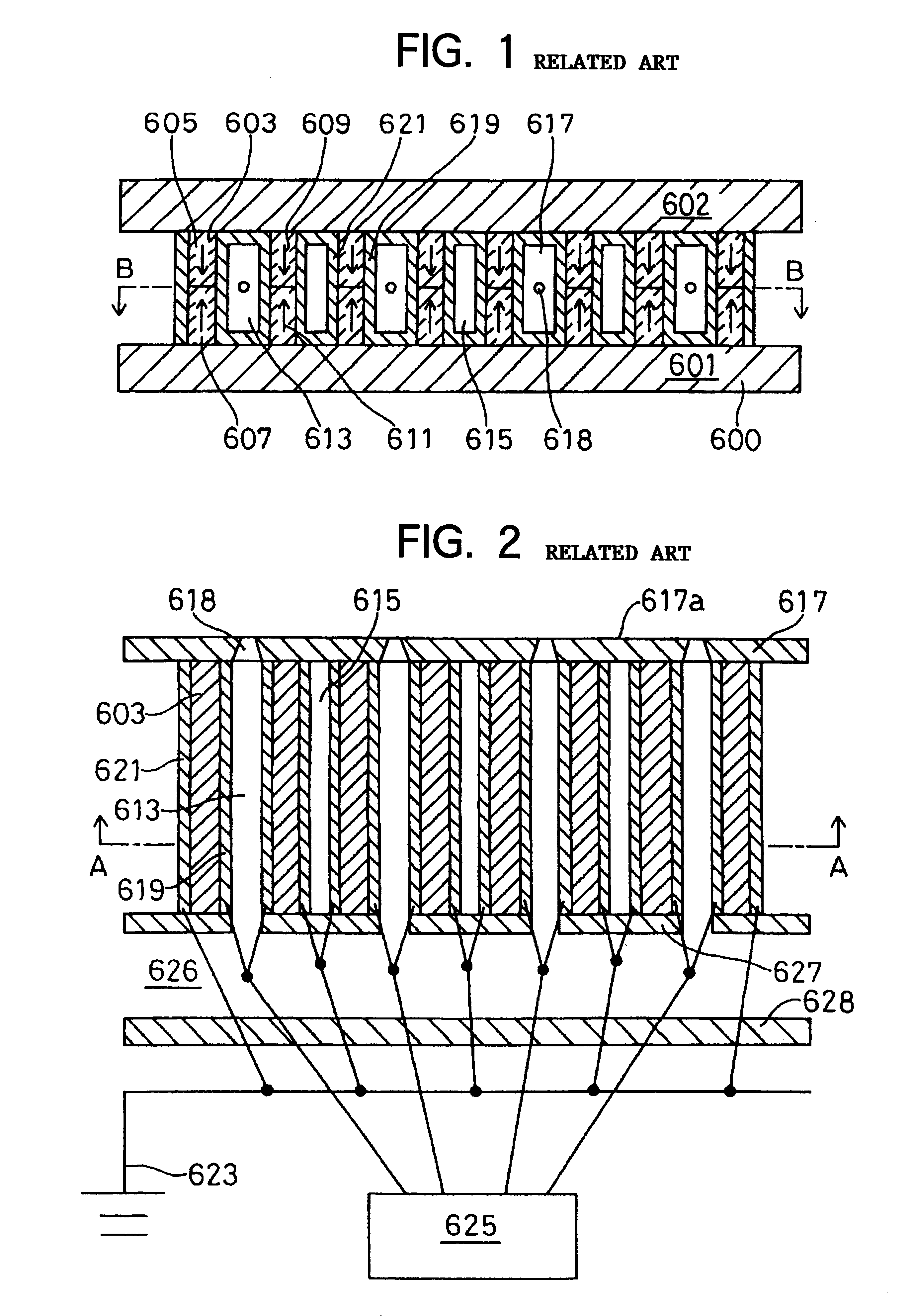
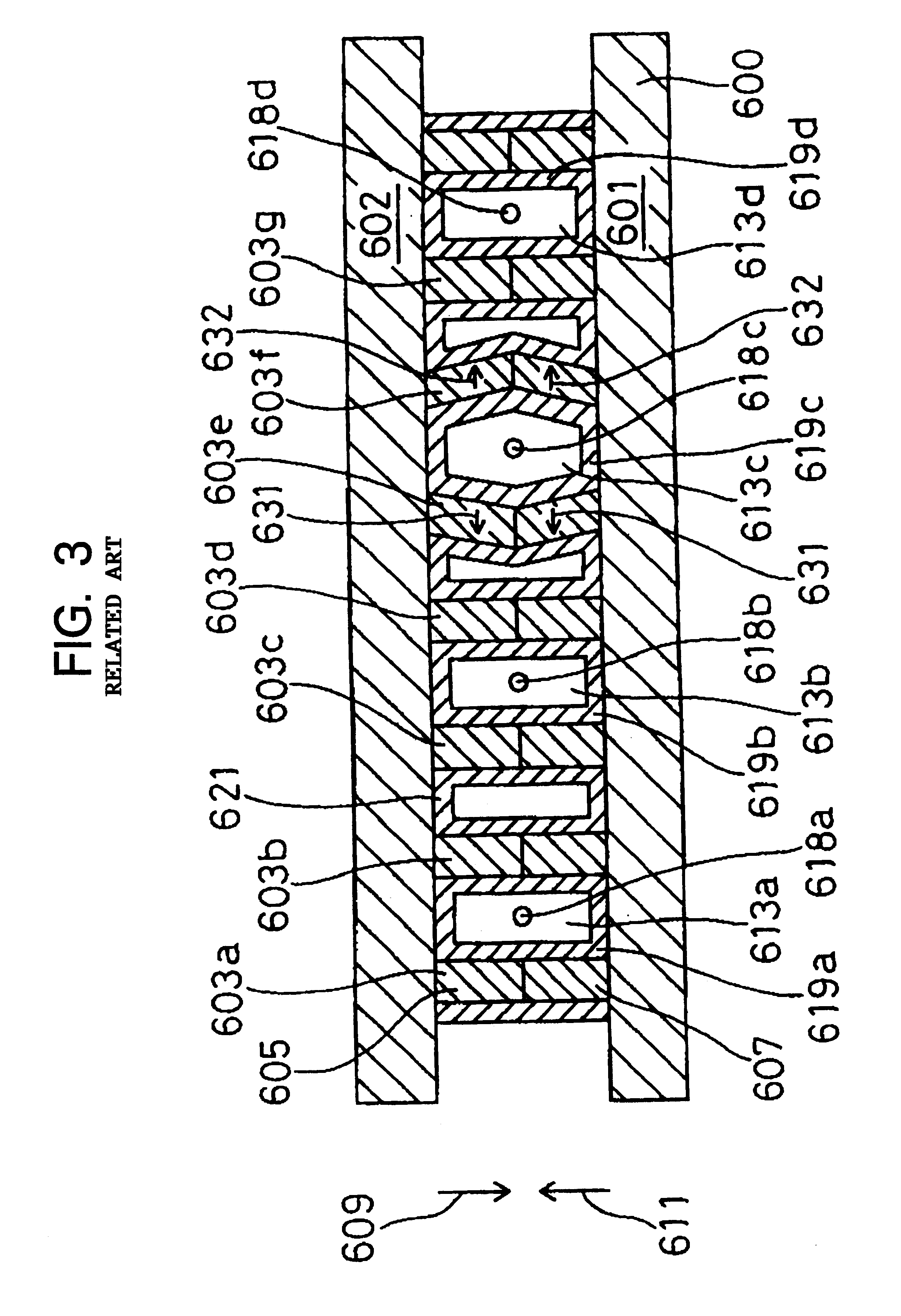
An ink ejecting device according to the present invention will be described while referring to FIGS. 1 and 2. FIG. 1 is a cross-sectional view taken along a line A--A of FIG. 2. FIG. 2 is a cross-sectional view taken along a line B--B of FIG. 1.

As shown in FIGS. 1 and 2, an ink ejection unit 600 is formed from a floor wall 601, a ceiling wall 602, and a plurality of shear mode actuator walls 603, which are disposed between the floor wall 601 and the ceiling wall 602. Each shear mode actuator wall 603 includes an upper wall 605 and a lower wall 607. The upper walls 605 are adhered to the ceiling wall 602 and are formed from piezoelectric material that is polarized in a direction indicated by an arrow 609. The lower walls 607 are adhered to the floor wall 601 and are formed from piezoelectric material that is polarized in a direction indicated by an arrow 611. The shear mode actuator walls 603 are organized in pairs. Each pair of actuator walls 603 forms therebetween an ink chamber 61...

second embodiment

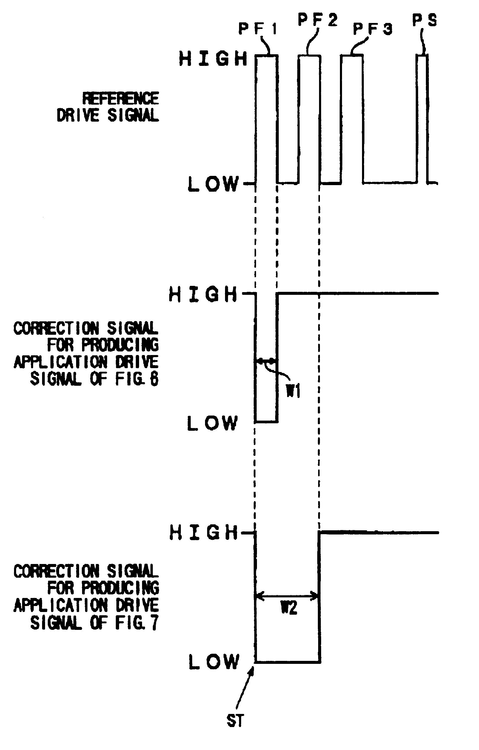
the reference data storage circuit 4 stores data corresponding to a single ejection pulse and data corresponding to a cancellation pulse.

Consequently, the drive signal generating circuit 6 produces only the single ejection pulse and the cancellation pulse. The drive signal correction circuit 8 repeatedly outputs the ejection pulse in the number of times indicated in the print command. Afterward, the cancellation pulse is outputted after a fixed predetermined duration of time.

In both the first and second embodiments, a desired number of ejection pulses are disposed toward the rear end of a predetermined maximum number of ejection pulses. When the maximum number of ejection is not required, then positions corresponding to ejection pulses are eliminated starting from the front end. For this reason, regardless of the desired number of ejections, the cancellations pulse is outputted after a fixed interval following the last ejection pulse.

In each embodiment, when a particular dot is to b...


PUM


Abstract

When a print data reception circuit 2 receives a print command, the print data reception circuit 2 transmits data indicating this to a drive signal generating circuit 6, and also transmits data indicating a desired member of ejections per dot to a drive signal correction circuit 8. Based on memory content of a reference data storage circuit 4, the drive signal generating circuit 6 produces a reference drive signal, which includes a predetermined maximum number of ejection pulses for printing each single dot, and transmits it to the drive signal correction circuit 8. The drive signal correction circuit 8 produces a print drive signal by removing unnecessary ejection pulses from the reference drive signal, in accordance with the desired number of ejection pulses indicated in the print command, and than transmits the print drive signal to a charge/discharge circuit 10. The charge/discharge circuit 10 controls electric potential difference between electrodes 619, 921 in accordance with high and low levels of the application drive signal. The piezoelectric material between the electrodes 619 and 621 deforms according to the electric potential difference, so that a desired number of ink droplets are ejected.

Description

1. Field of the InventionThe present invention relates to an ink ejecting device for forming images on a recording medium, such as paper, by ejecting ink from nozzles in accordance with print commands.2. Description of the Related ArtInk jet printers are a type of non-impact printer. They are based on the simplest operation principle and are also easily adapted for both tonal and color printing. Drop-on-demand type ink jet printers, which eject only ink required for printing, have good ejection efficiency and low running costs and so are becoming rapidly more popular. Conventional ink ejection units are described in U.S. Pat. Nos. 4,879,568, 4,887,100, 4,992,808, 5,003,679, and 5,028,936 and in Japanese Patent Application Publication (Kokai) No. SHO-63-247051, which corresponds at least partially to all of these U.S. patents.Next, an explanation will be provided for an exemplary conventional shear mode type ejection unit that uses piezoelectric material for ejecting ink droplets. Th...

Claims


Application Information

Patent Timeline
IPC IPC(8): B41J2/045B41J2/055B41J2/205
CPCB41J2/04581B41J2/04588B41J2/04591B41J2/04595B41J2202/10
Inventor ISHIKAWA, HIROYUKI
Owner BROTHER KOGYO KK
Why Eureka
Try Eureka