Network fault information management system in which fault nodes are displayed in tree form

Inactive Publication Date: 2002-12-24
NEC CORP
View PDF13 Cites 83 Cited by
  • Summary
  • Abstract
  • Description
  • Claims
  • Application Information

AI Technical Summary

Problems solved by technology

However, it is not possible to show what fault occurs where in the apparatus on the same screen.
Especially, when a plurality of faults which have occurred in a plurality of network management systems should be displayed, the number of times of the changing operation of the display screen increases.
Therefore, in the c

Method used


Image

  • Network fault information management system in which fault nodes are displayed in tree form
  • Network fault information management system in which fault nodes are displayed in tree form
  • Network fault information management system in which fault nodes are displayed in tree form

Examples


operation example 2

(Operation Example 2)

Next, a specific operation example 2 will be described with reference to FIG. 10. In the operation example 2, the following matters are supposed. That is, the fault association notice (alarm) 40 received from a network element in the network contains a fault occurrence not identifier 41 showing a fault occurrence location of "2". Moreover, the fault association notice 40 contains as the fault data 42, a fault classification 421 of the voltage drop, fault occurrence date and time 423 of 9:26:30 a.m. on August 31, and a fault importance level 422 of a restoration notice.

The operation example in such conditions will be described.

First, the fault data receiving section 21 takes out the identifier 41 of "2" from the received fault association notice (step A1), and starts the searching operation of the tree structure of the fault node data (Step A2).

As the result of the searching operation, when the node having the identifier of "2" in the level 1 is found out, i.e., ...

second embodiment

Next, the second embodiment of the present invention will be described with reference to FIG. 11.

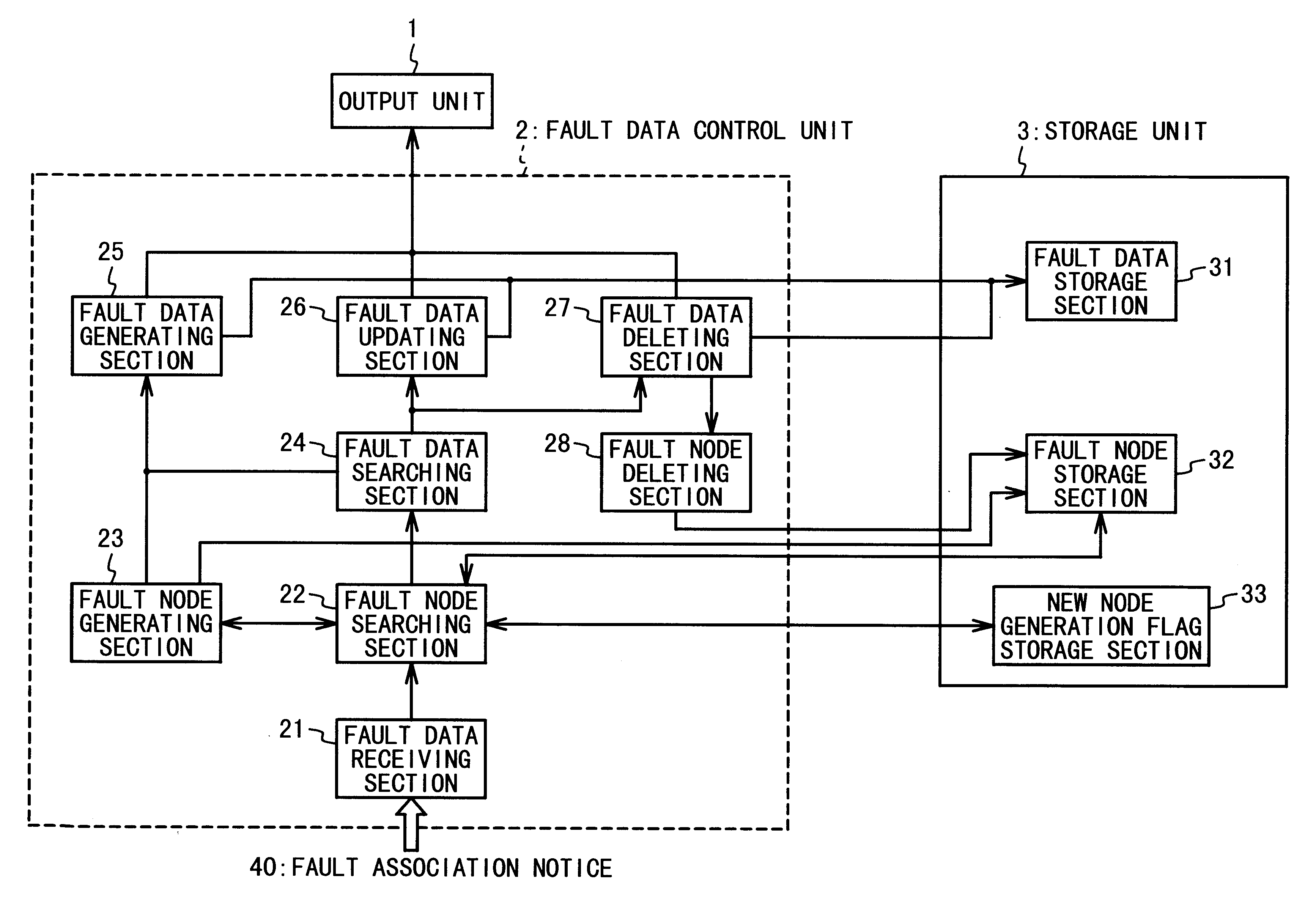
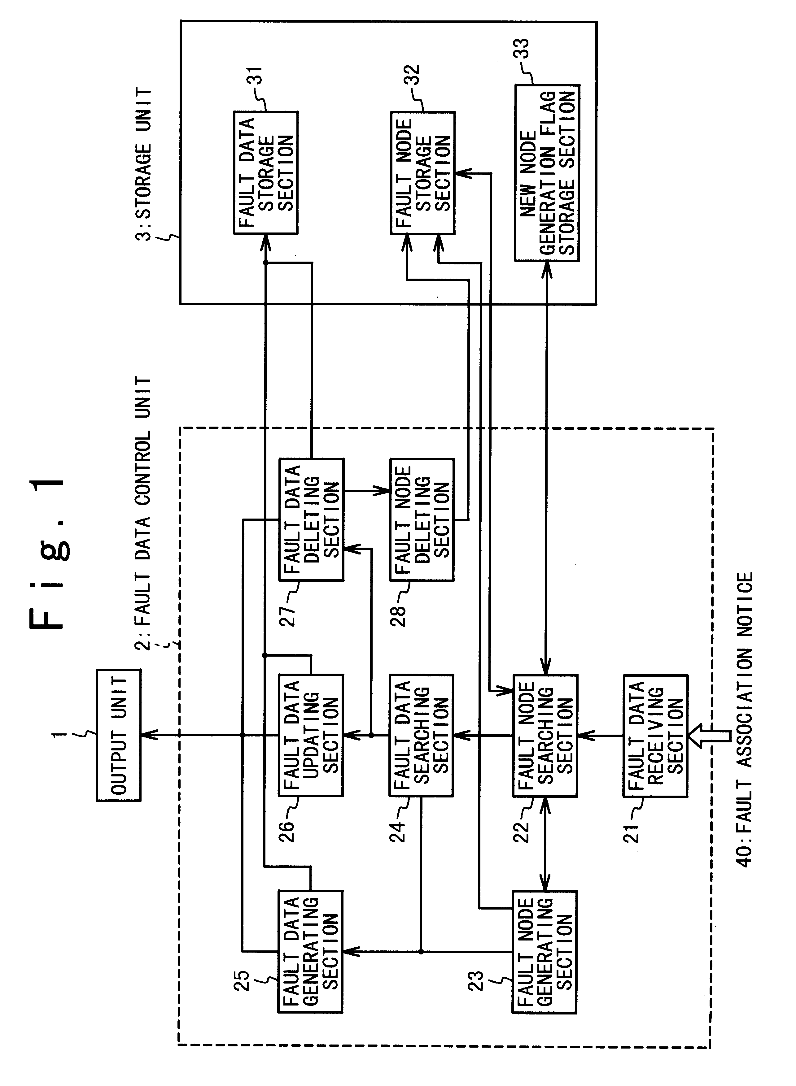
As shown in FIG. 11, the network fault data management system in the second embodiment has an input unit 4 such as a keyboard and a mouse, a fault data display control unit 29 in the fault data control unit 2 and a display data storage section 34 in the storage unit 3 in addition to the structure of the first embodiment.

Then, the input unit 4 operates to receive an operation command of the fault node data tree structure from an operator.

Also, the fault data display control unit 29 controls the output unit 1 to display in the tree structure, the fault data which have been processed by the fault data generating section 25, the fault data updating section 26 and the fault data deleting section 27 which are shown in the first embodiment of the present invention, in response to a display demand of the fault node data tree from the operator.

As shown in FIG. 12, the display data storage section...


PUM


Abstract

A network fault managing system for a network including network elements as nodes includes a fault node indication data storage section, a fault indication data storage section, a flag, a fault node indication data processing section, a fault indication data processing section and an output unit. The fault node indication data storage section stores a fault node indication data set in which fault nodes are managed in a tree form. The fault node indication data processing section receives a fault association notice having a fault occurrence position identifier and a fault indication data, the fault occurrence position identifier indicating a fault node in which a fault has occurred, and the fault indication data indicating data associated with the fault, and determines whether a fault node indication data corresponding to the fault node specified by the fault occurrence position identifier of the fault association notice is present in the fault node indication data set. Also, the fault node indication data processing section generates the fault node indication data based on the fault occurrence position identifier to store in the fault node indication data set of the fault node indication data storage section, when the fault node indication data is not present in the fault node indication data set, and sets the flag.

Description

1. Field of the InventionThe present invention relates to a network management system. More particularly, the present invention is directed to a network management system to manage the state of a fault network element and to notify a fault occurrence location in a large-scale communication network.2. Description of the Related ArtAn conventional example of a network fault management system will be described in Japanese Laid Open Patent Application (JP-A-Heisei 5-33692). According to the system described in this reference, the state of a fault is checked based on a structure data of a tree form. That is, a knowledge base is previously prepared to store a fault diagnostic tree in which nodes represent various fault states. The fault diagnostic tree is traced based on fault data received from an apparatus in which any fault has occurred, to specify a kind of the fault.Also, in the large-scale network, distribution management is generally used for the network fault management system. In...

Claims


Application Information

Patent Timeline
IPC IPC(8): H04L12/24G06F13/00G06F11/22H04L12/70
CPCH04L41/0654H04L41/0677
Inventor TANAKA, KATSUYUKI
Owner NEC CORP
Why Eureka
Try Eureka