Variable compression ratio connecting rod locking mechanism I

Inactive Publication Date: 2002-12-31
FORD GLOBAL TECH LLC
View PDF17 Cites 28 Cited by
  • Summary
  • Abstract
  • Description
  • Claims
  • Application Information

AI Technical Summary

Problems solved by technology

A gasoline engine whose compression ratio remains invariant as operating conditions change is said to be knock-limited.
However, those conditions that give rise to engine knocking in a motor vehicle typically prevail for only limited times as the vehicle is being driven.
At oth

Method used


Image

  • Variable compression ratio connecting rod locking mechanism I
  • Variable compression ratio connecting rod locking mechanism I
  • Variable compression ratio connecting rod locking mechanism I

Examples


first embodiment

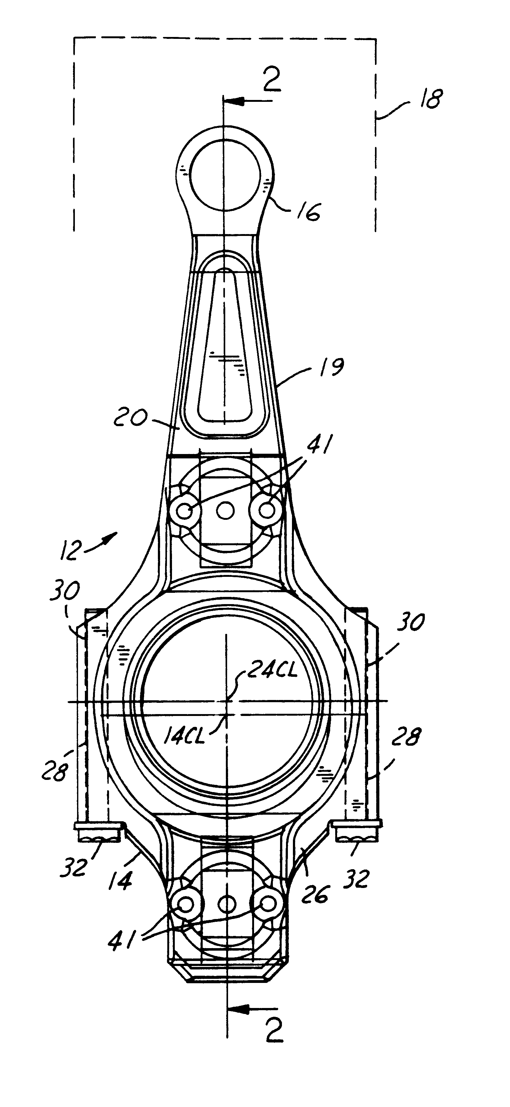
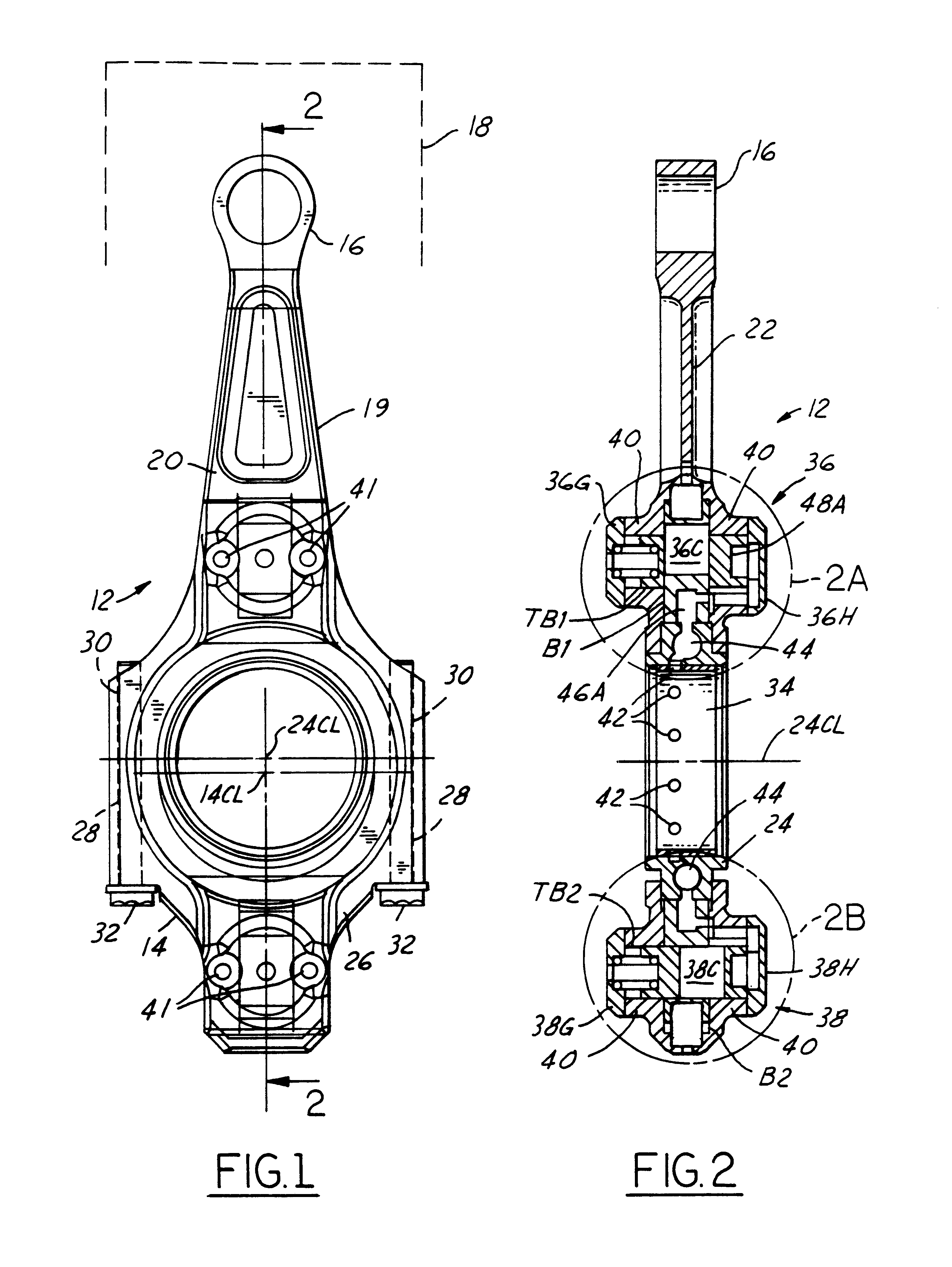
FIGS. 1 and 2 show variable length connecting rod assembly 12 for endowing an engine with a variable compression ratio. Connecting rod assembly 12 comprises a large end 14 for journaling on a crank pin of a crankshaft and a small end 16 for journaling on a central portion of a wrist pin for coupling the connecting rod assembly to a piston 18 (schematically shown in FIG. 1 only). A variable length mechanism is embodied in large end 14 to provide for changing the effective length of connecting rod assembly 12.

second embodiment

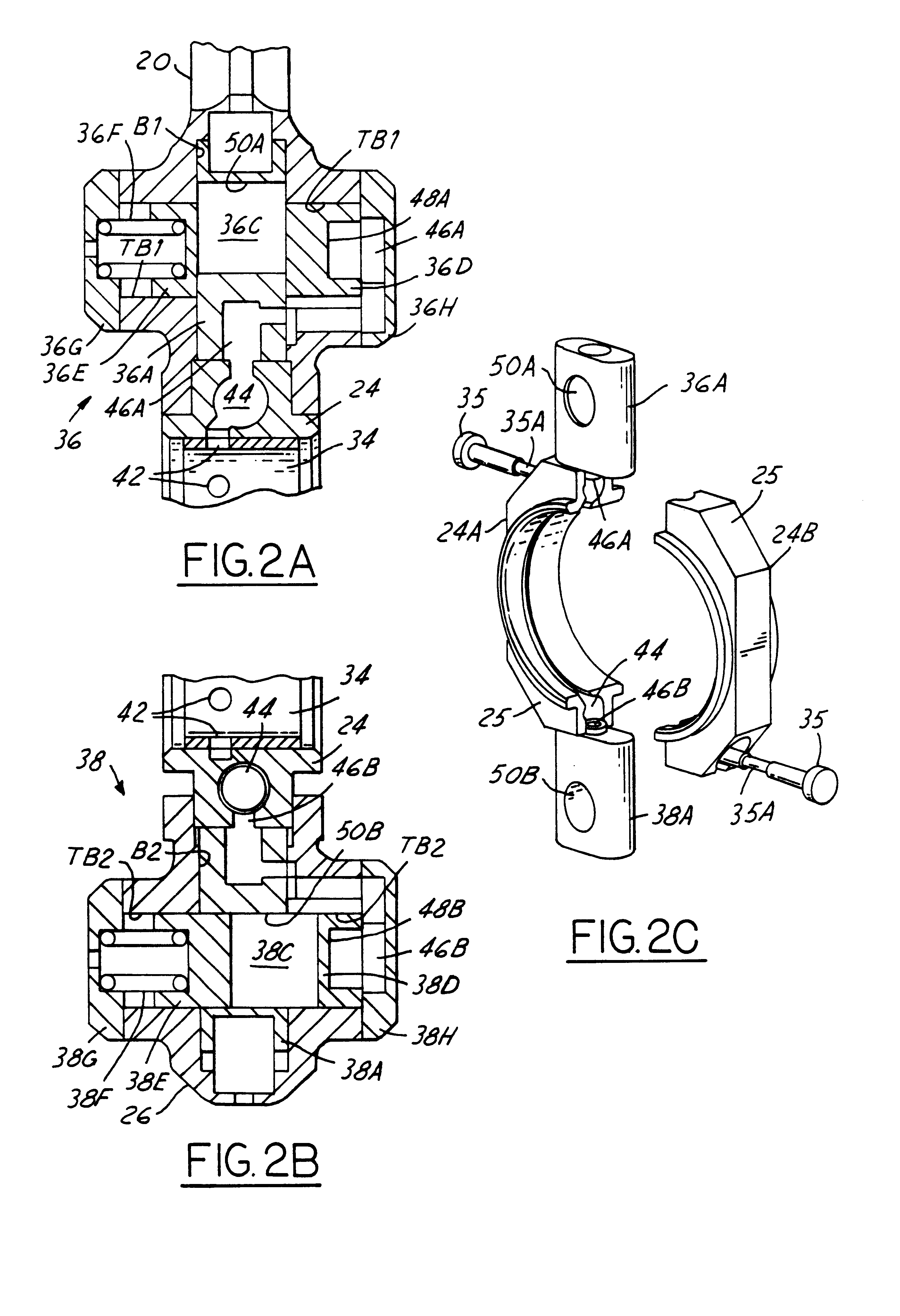
Connecting rod assembly 12 comprises a fixed length connecting rod 19 formed by two parts 20 and 26 that are fastened together. One end of part 20 contains small end 16 and a rod portion 22 that extends from the small end to large end 14. The variable length mechanism is like the second embodiment disclosed in the referenced commonly owned patent application and is provided by a bearing retainer 24 which is assembled onto a crank pin of a crankshaft with its centerline concentric with that of the crank pin. Bearing retainer 24 is captured between a somewhat semi-circular portion of part 20 at large end 14 and a somewhat semi-circular cap that forms part 26. Opposite ends of the semi-circumference of part, or cap, 26 contain holes 28 that align with holes 30 in part 20. Fasteners 32 fasten cap 26 to part 20 via holes 28, 30. Cap 26 and part 20 have channels that fit to respective portions of a flange 25 of bearing retainer 24 (see FIG. 2C).

The channel and flange depths are chosen to ...

third embodiment

The third embodiment shown in FIG. 7 and 7A possesses locking mechanisms 36, 38 that are somewhat different from those of the first two embodiments. Elements of the third embodiment that are similar to those of the first two embodiments are identified by the same corresponding reference numerals, and it is believed that detailed descriptions are unnecessary, except for relevant differences.

FIG. 7 shows the connecting rod in the high compression ratio default position where locking mechanism 36 is locked while locking mechanism 38 is unlocked. Locking mechanism 36 comprises two lock pins 36C1, 36C2. A respective spring 36J1, 36J2 is associated with a respective lock pin. A cylindrical spacer sleeve 36K is disposed in through-hole 50A. Control passage 46A is open within part 20 to through-hole 50A, and sleeve 36K contains a through-hole TH1 that allows the control passage to be open to the interior of the spacer sleeve, and hence also the interior of through-hole 50A.

Each lock pin com...


PUM


Abstract

A variable length connecting rod (12) has a first locking mechanism (36) for releasably locking connecting rod parts in a first effective length setting (FIG. 3) for the rod, and a second locking mechanism (38) for releasably locking the connecting rod parts in a second effective length setting (FIG. 2) to change the compression ratio for an engine cylinder. When a length change is to be made, hydraulic fluid unlocks a locked one of the locking mechanisms, allowing inertial force to effect the length change during an engine cycle. At completion of a length change, the other locking mechanism automatically unlocks.

Description

This invention relates generally to reciprocating piston type internal combustion (I.C.) engines for motor vehicles. More specifically it relates to I.C. engines having variable compression ratio connecting rods, especially to systems, mechanisms, and strategies for operating a connecting rod to different compression ratios while an engine is running.BACKGROUND INFORMATIONA gasoline engine whose compression ratio remains invariant as operating conditions change is said to be knock-limited. This means that the compression ratio built into the engine design must be selected to avoid objectionable engine knock that would otherwise occur during certain conditions of engine operation if the compression ratio were larger. However, those conditions that give rise to engine knocking in a motor vehicle typically prevail for only limited times as the vehicle is being driven. At other times, the engine could operate with better efficiency, and still without knocking, if the compression ratio c...

Claims


Application Information

Patent Timeline
IPC IPC(8): F02B75/00F02B75/04F16C7/00F16C7/02
CPCF02B75/045F16C7/02
Inventor RAO, V. DURGA NAGESWARMADIN, MARK MICHAELIMAI, YASH ANDREW
Owner FORD GLOBAL TECH LLC
Why Eureka
Try Eureka