
Ultra-lean dilution apparatus

Inactive Publication Date: 2002-12-31
DELAWARE CAPITAL FORMATION
View PDF37 Cites 53 Cited by
  • Summary
  • Abstract
  • Description
  • Claims
  • Application Information

AI Technical Summary

Benefits of technology

Accordingly, it is an object of the present invention to provide an ultra-lean dilution apparatus for proportioning minute quantities of a first fluid, such as a concentrated cleaning solution, for mixing into a second fluid, such as tap water, which provides improved performance and which can be manufactured by assembling several molded components with little or no machining.
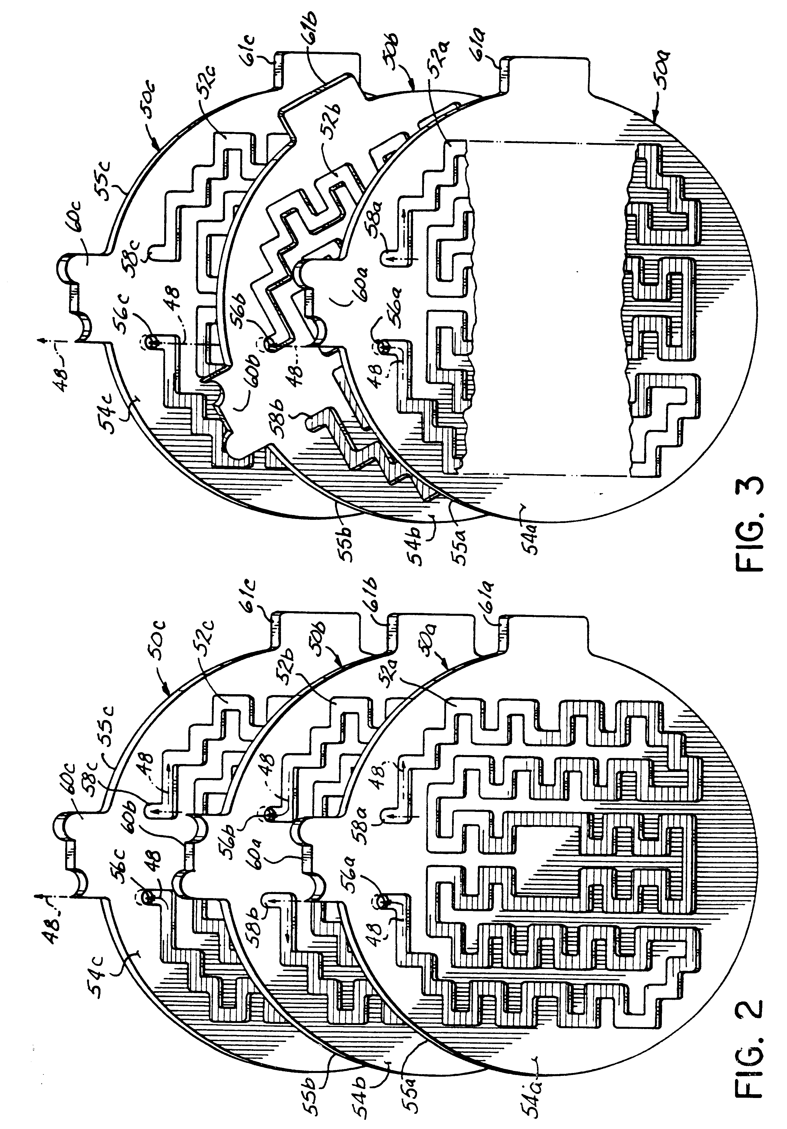
In yet a further aspect of the invention, a stack of dilution disks molded from economical elastomeric material are compressed together within an engagable housing including a window access for selectively positioning or rotating each disk into or out of the fluid circuit and to verify the setting of each disk, wherein, once engaged, the housing locks the disks into position. Advantageously provided are a positioning tab and an alignment tab, both peripherally located on each disk. The positioning tab allows for rotatably positioning, and verifying the position, of each disk within the window of the housing. The alignment tab cooperates with an alignment groove within the housing to constrain the range of rotation of each disk such that the two rotation extremes allowed correspond to an engaged and a bypass position for the disk.
In yet another aspect of the invention, a rotatable dilution disk is separated from another rotatable dilution disk by a fixed dilution disk, wherein the respective alignment tab is substantially constrained by the alignment groove of the housing. Movement of a rotatable dilution disk is thus prevented from inadvertently moving other rotatable dilution disks.

Problems solved by technology

Yet in this range many particles or artifacts in chemicals may clog them.
Thus, such metering orifices are generally not used.

Method used


Image

  • Ultra-lean dilution apparatus
  • Ultra-lean dilution apparatus
  • Ultra-lean dilution apparatus

Examples


Embodiment Construction

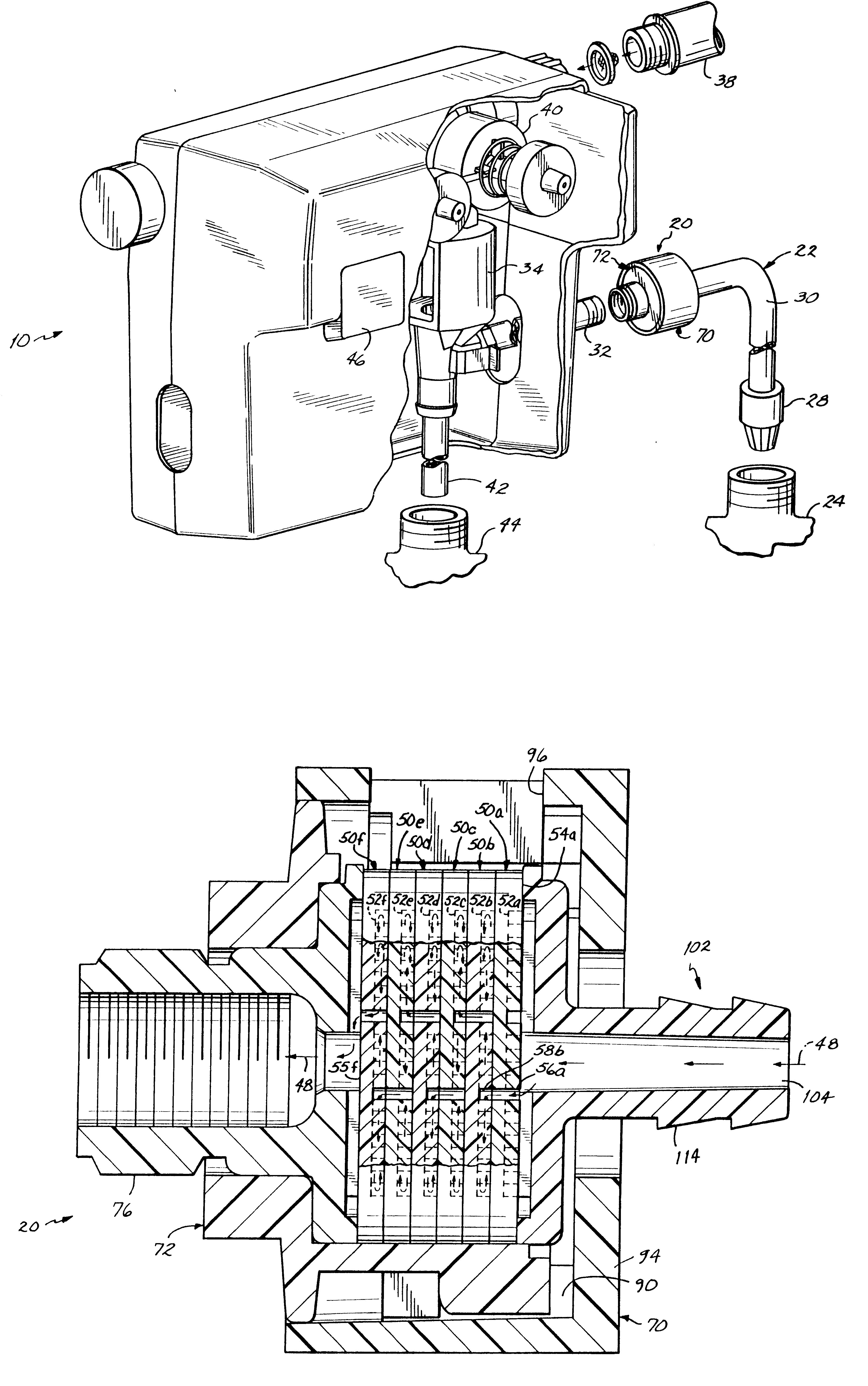
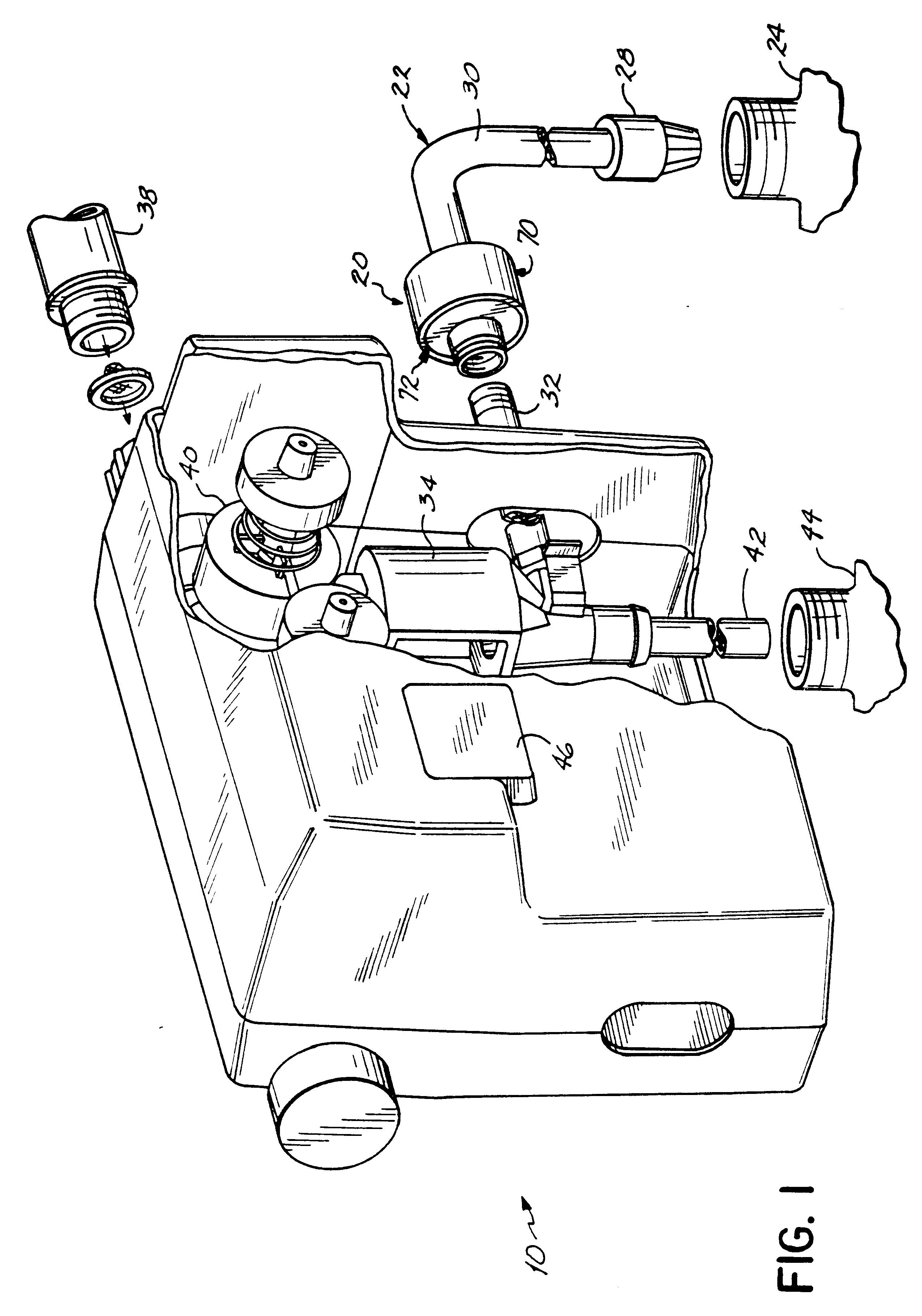
Referring to FIG. 1, a dispensing system 10, also referred to as a proportioner unit, is shown incorporating an ultra-lean dilution apparatus 20 for proportioning a first fluid, a concentrated liquid chemical such as a cleaning solution. The dilution apparatus 20 meters the flow of concentrated liquid chemical from a concentrated liquid reservoir 24 into a carrier stream such as water by selectively controlling the pressure drop in a supply conduit 22. Flow from the concentrated liquid reservoir 24 passes through a foot valve 28, which minimizes back flow, through tubing 30 to the dilution apparatus 20. After the flow is metered by the dilution apparatus 20, flow continues through eductor tubing 32 to an air gap eductor 34, such as described in the aforementioned U.S. Pat. Nos. 5,522,419, 5,253,677 5,159,958, and 5,862,829. Thus, conduit 22 is shown as including the foot valve 28, tubing 30, dilution apparatus 20, and eductor tubing 32.

The eductor 34 provides a venturi function for ...


PUM


Abstract

An ultra-lean dilution apparatus is provided for proportioning minute quantities of a first fluid, such as a concentrated cleaning solution, for mixing into a second fluid, such as tap water, which provides improved performance and which can be manufactured by assembling several molded components with little or no machining. The dilution apparatus (20) provides a selective pressure drop in a conduit (22) by including a plurality of dilution disks (50a-50f), each dilution disk (50a-50f) having a tortuous path (52a-52f) of sufficient cross-sectional area to be resistant to clogging and having a sufficient number of sharp turns to create a desired pressure drop. While each disk (50a-50f) produces a predetermined drop, the serial configuration of the tortuous paths of the plurality of dilution disks is additive to produce a range of dilution suitable for the chemicals used. Advantageously, the tortuous path of a first of the plurality of dilution disks (50a) is recessed into a front face so that bringing the front face (54a) of the first dilution disk (50a) in contact with a back face (55b) of a second dilution disk (50b) completes the tortuous path (52a). Furthermore, a blind intake (58a) of the tortuous path (52a) of the first dilution disk (50a-50f) selectively communicates with an output port (56b) of another tortuous path (52b) on a front face (54b) the second dilution disk (50b).

Description

BACKGROUND OF THE INVENTION1. Field of the InventionThis invention relates to devices for dispensing and mixing liquids, and more particularly to such devices that dispense and mix chemicals, and even more particularly to devices that dispense and mix cleaning chemicals.2. Prior ArtIt is common practice to purchase concentrated cleaning chemicals and to mix them with other liquids such as water to achieve the desired usage concentration for cleaning. A variety of proportioning dispensers have been developed to achieve this. The dispensers often employ venturi-type devices sometimes called eductors to draw the concentrated liquid chemical and mix it with the water stream. Examples of such eductors include the Sand U.S. Pat. Nos. 5,522,419, 5,253,677 5,159,958, and 5,862,829 all of which are assigned to the Assignee of the present invention and are expressly incorporated herein. Water traveling through the central, constricted portion of the venturi creates suction which draws the con...

Claims


Application Information

Patent Timeline
IPC IPC(8): A01G25/02B01F5/04B01F5/06
CPCA01G25/023B01F5/0415B01F5/043B01F5/0604Y10T137/0801B01F25/3121B01F25/31243B01F25/422
Inventor SAND, WILLIAM F.
Owner DELAWARE CAPITAL FORMATION
Learn More