Turbo-molecular pump having enhanced pumping capacity

a vacuum pump and turbomolecular technology, applied in the field of micro-molecular vacuum pumps with increased pumping capacity, can solve the problems of pump components failing, plasma-based etching and cvd processes requiring particularly high process gas flow rates and relatively shallow vacuum levels, and the cost of building and maintaining clean rooms is so high

Inactive Publication Date: 2003-01-07
APPLIED MATERIALS INC
View PDF10 Cites 18 Cited by
  • Summary
  • Abstract
  • Description
  • Claims
  • Application Information

AI Technical Summary

Problems solved by technology

Because the cost of building and maintaining clean rooms is so expensive, the physical size of components therein, including the turbo molecular pumps is always critical.
Some substrate processes like plasma-based etch and CVD processes require particularly high process gas flow rates and relatively shallow vacuum levels.
However, increasing the rotational speed of a rotor and the rotor blades necessarily results in additional stresses on the rotor and other components that can lead to failure of the pump components.
Additionally, because of the high throughput of the process gases through the vacuum pump, unused reactants as well as reaction byproducts are removed from the processing chamber at a high rate and can either adhere to or react with the surfaces of the components inside the vacuum pump, causing the components to heat up significantly and resulting in breakdown of the component and the pump.
For example, in HDP applications the pump internal components, such as a rotor, can rise to a temperature above 120.degree. C., and the stress caused by the high temperature can cause a physical break down of the component and the pump.
Therefore, simply increasing the rotational speed of the pump is not a realistic solution.
The larger pumps are more expensive to build, use additional energy to operate and cause more vibration in the clean room.
Further, the larger pumps take up more of the precious envelope and clean room space below the vacuum chamber, giving the apparatus a larger footprint.

Method used


Image

  • Turbo-molecular pump having enhanced pumping capacity
  • Turbo-molecular pump having enhanced pumping capacity
  • Turbo-molecular pump having enhanced pumping capacity

Examples


Embodiment Construction

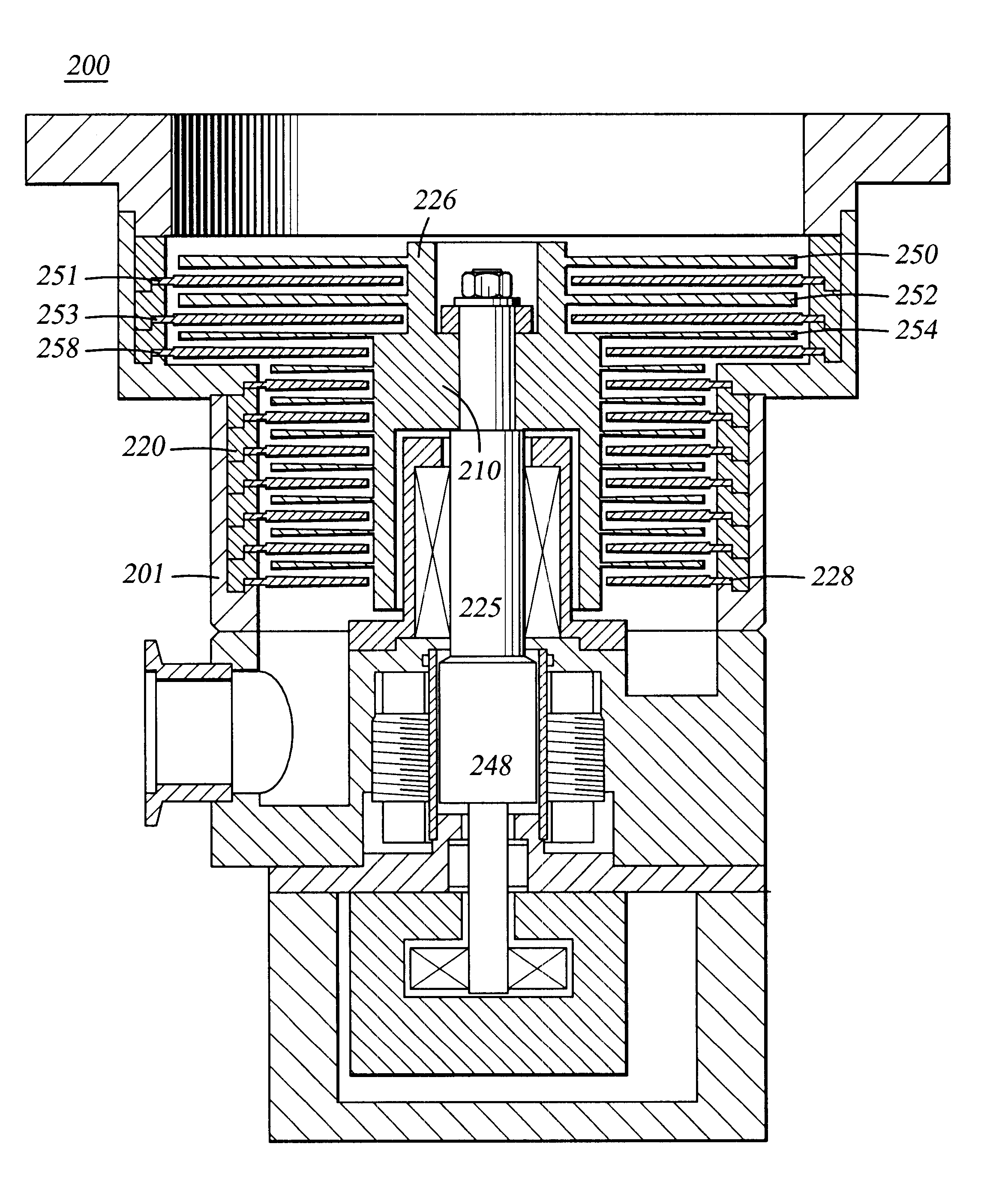
FIG. 3 is a cross-sectional view showing one embodiment of the pump 200 of the present invention. The pump includes a stator 220 extending radially inwardly from the casing 201 and a rotor 210 disposed within the casing. A motor 248 is coaxially disposed with the rotor and rotates the rotor 210 about a shaft 225. The rotor 210 includes two outer diameters, a smaller diameter 226 adjacent an inlet 205 of the pump and a lower, larger diameter 228 extending towards an outlet 206 of the pump. In the embodiment illustrated in FIG. 3, the first two rows of rotor blades 250, or those blades extending from the smaller diameter portion 226 of the rotor 210, have an increased length as compared to the other rotor blades 225 extending from the larger diameter 228 of the rotor 225. The corresponding stator blades 251 are also increased in length extending inwards from an enlarged diameter portion 253 of the stator 220. The longer stator and rotor blades 250, 251 provide an increased surface are...


PUM


Abstract

In one aspect, a vacuum processing system comprising a vacuum processing chamber and a turbo-molecular pump disposed on the vacuum processing chamber is provided. The turbo-molecular pump comprises a casing having an inlet port and an outlet port, a stator disposed on an inner wall of the casing, a rotor disposed in the stator, and a motor extending coaxially with the rotor, wherein at least the first stage of the pump is enlarged with no correspondingly larger pump components other than the corresponding upper portion of the housing.

Description

1. Field of the InventionThe present invention generally relates to semiconductor processing. Specifically, the present invention relates to semiconductor processing equipment and a turbo-molecular vacuum pump with increased pumping capacity for evacuating a vacuum processing chamber.2. Background of the Related ArtSubstrates are typically processed through various etch, chemical vapor deposition (CVD), physical vapor deposition (PVD), ion implanting and cleaning steps to construct integrated circuits or other structures thereon. These steps are usually performed in an environmentally isolated and vacuum sealed substrate processing chamber. The substrate processing chamber generally comprises an enclosure having a side wall, a bottom and a lid. A substrate support member is disposed within the chamber to secure a substrate in place during processing by electrical or mechanical means such as an electrostatic chuck or a vacuum chuck. A slit valve is disposed on a chamber side wall to ...

Claims


Application Information

Patent Timeline
Patent Type & Authority Patents(United States)
IPC IPC(8): F01D1/00F01D1/36F04D19/04
CPCF04D19/042F01D1/36F04D29/324F04D29/547F04D21/00F04D19/04
Inventor REIMER, PETERSMITH, DENNIS R.PATEL, JAY
Owner APPLIED MATERIALS INC
Why Eureka
Try Eureka