Rotary switch having click mechanism

a click mechanism and rotary switch technology, applied in the direction of resistors with sliding contact, adjustable resistors, resistors, etc., can solve the problem of large noise at the time of manipulation of switching sounds (an impinging sound)

a click mechanism and rotary switch technology, applied in the direction of resistors with sliding contact, adjustable resistors, resistors, etc., can solve the problem of large noise at the time of manipulation of switching sounds (an impinging sound)

US6506984B2Inactive Publication Date: 2003-01-14ALPS ALPINE CO LTD

Image

  • Rotary switch having click mechanism
  • Rotary switch having click mechanism
  • Rotary switch having click mechanism

Examples


Embodiment Construction

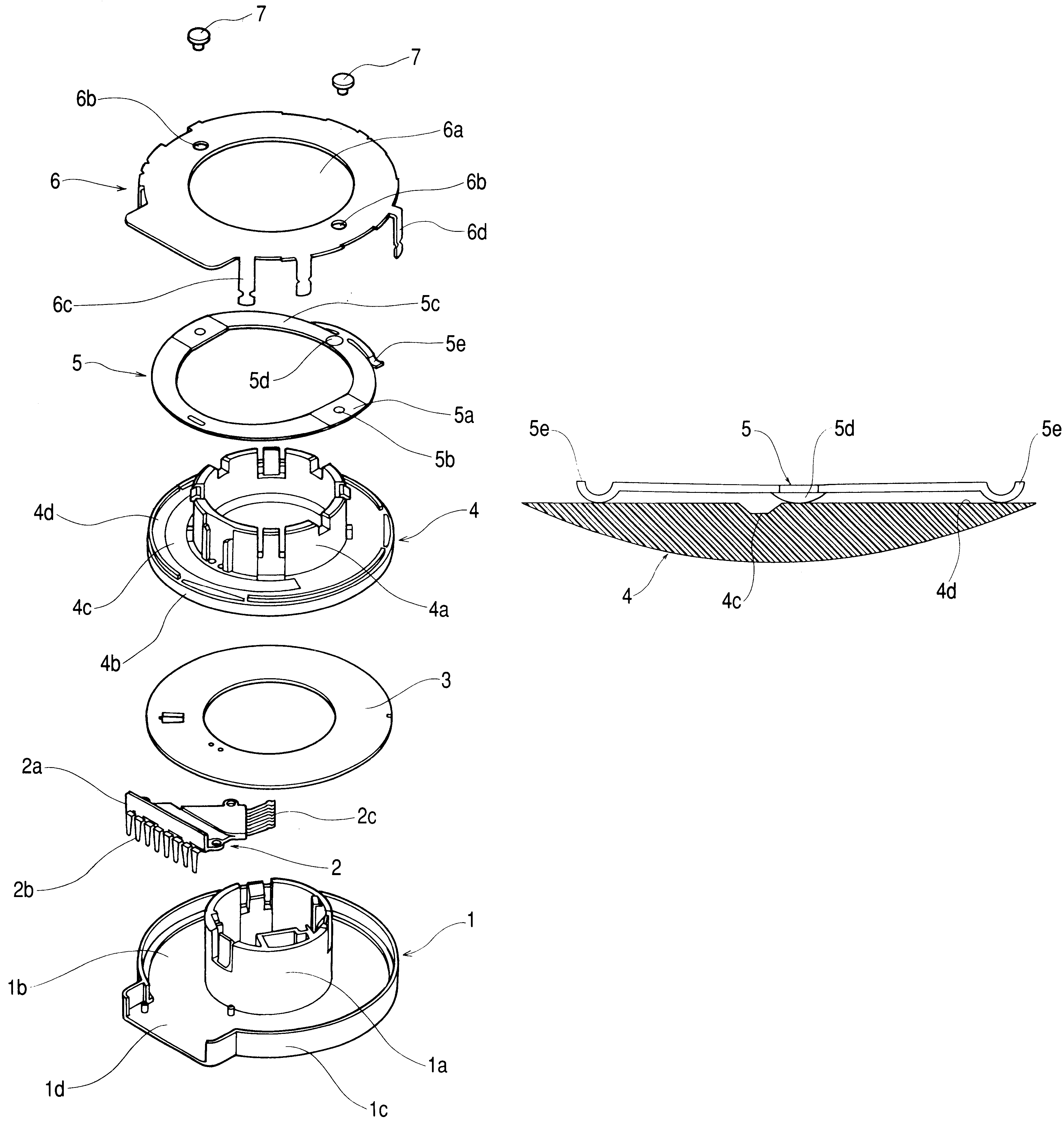
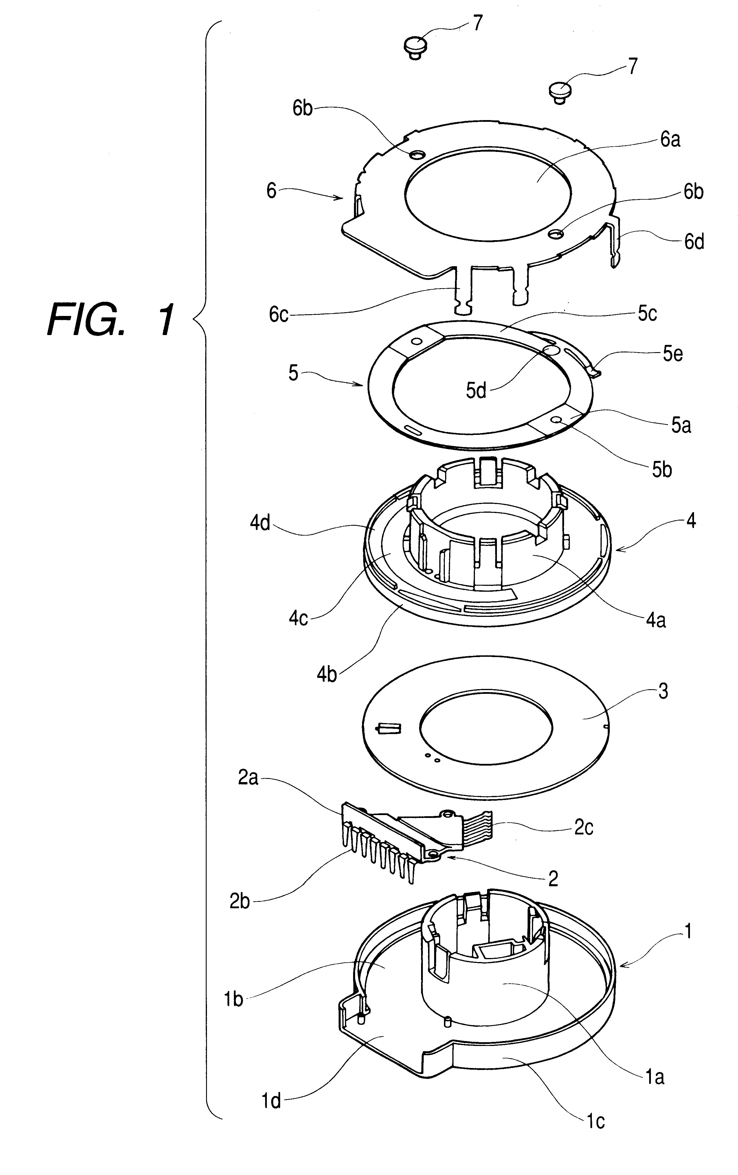
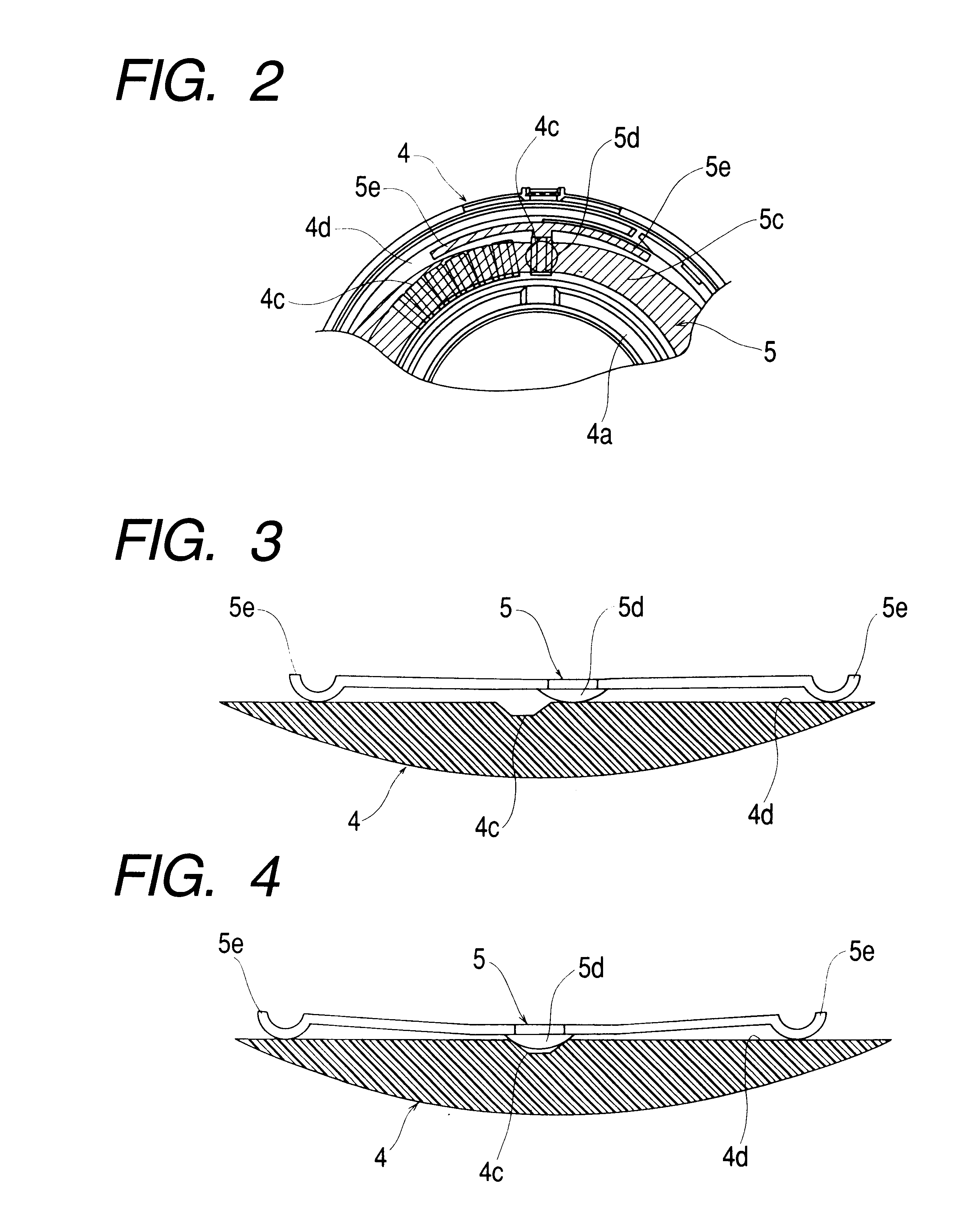
One embodiment of the present invention is shown in FIG. 1 to FIG. 4. FIG. 1 is an exploded perspective view showing a rotary switch device, FIG. 2 is a partial explanatory view showing the relationship between a cam surface and a spring member, FIG. 3 is a partial explanatory view showing the state in which a projection of the spring member is positioned at a plateau of the cam surface, and FIG. 4 is a partial explanatory view showing the state in which the projection of the spring member is positioned at a valley of the cam surface.

In the drawings, a housing 1 is made of insulation material such as synthetic resin or the like and is substantially formed in an annular shape having a hollow portion at the center thereof. A hollow cylindrical support shaft 1a is formed at the center of the housing 1, while a base disc portion 1b which has an accommodating portion 1b of an approximately annular shape with an open upper surface is formed at the lower end side of the support shaft 1a. F...


PUM


Abstract

A switch device reduces a switching sound (an impinging sound) at the time of manipulation with a constitution of a click mechanism which uses a spring member having a projection which is brought into slide contact with a cam surface formed of plateaus and valleys. The switch device includes a manipulating member having a cam surface which is formed of plateaus and valleys arranged contiguously and alternately and a spring member having the projection and generating a click feeling when the projection is brought into slide contact with the plateaus and the valleys of the cam surface. The spring member is provided with an auxiliary spring which is brought into slide contact with the manipulating member corresponding to the slide contact of the projection with the plateaus and the valleys of the cam surface. An auxiliary spring receiving portion with which the auxiliary spring is brought into slide contact is formed in the vicinity of the cam surface.

Description

1. Field of the InventionThe present invention relates to a switch device, and more particularly to a structure of a rotary switch device having a click mechanism which is used in various electronic equipment for household or vehicle mounting.2. Description of the Prior ArtA structure of a conventional rotary switch device having a click mechanism is shown in FIG. 5. FIG. 5 is an exploded perspective view of the rotary switch device.This conventional rotary switch device includes a resin-made housing 11 which has a support shaft 11a at the center of an accommodating portion 11b, a fixed terminal portion 12 which is arranged in the accommodating portion 11b of the housing 11, a circuit board 13 which has a contact portion which is brought into slide contact with a slider 12a of the fixed terminal portion 12, a rotary manipulating portion 14 which has the circuit board 13 fixedly secured to a lower surface side thereof, is rotatably supported on the support shaft 11a of the housing 11...

Claims


Application Information

Patent Timeline
14 Jan 2003
Publication
US6506984B2
IPC
H01H19/58; H01H19/00; H01H3/52; H01H19/11; H01H19/14; H01H19/20; H01H19/56
CPC
H01H19/585; H01H19/20
Inventors
TOMITA, KOJI