Pliers

a technology of pliers and pliers, which is applied in the field of pliers, can solve the problems of increasing the risk of injury, exposing parts of the row of teeth and catching, and not being particularly compact pliers

Inactive Publication Date: 2003-01-21
WEIDMULLER INTERFACE GMBH & CO KG
View PDF11 Cites 20 Cited by
  • Summary
  • Abstract
  • Description
  • Claims
  • Application Information

AI Technical Summary

Problems solved by technology

This results in the second plier handle, which accommodates the row of teeth and catch, having to be of relatively large design, which results in pliers which are not particularly compact.
A reduction in size of the second plier handle would bring with it the risk of exposing parts of th

Method used


Image

  • Pliers
  • Pliers
  • Pliers

Examples


Embodiment Construction

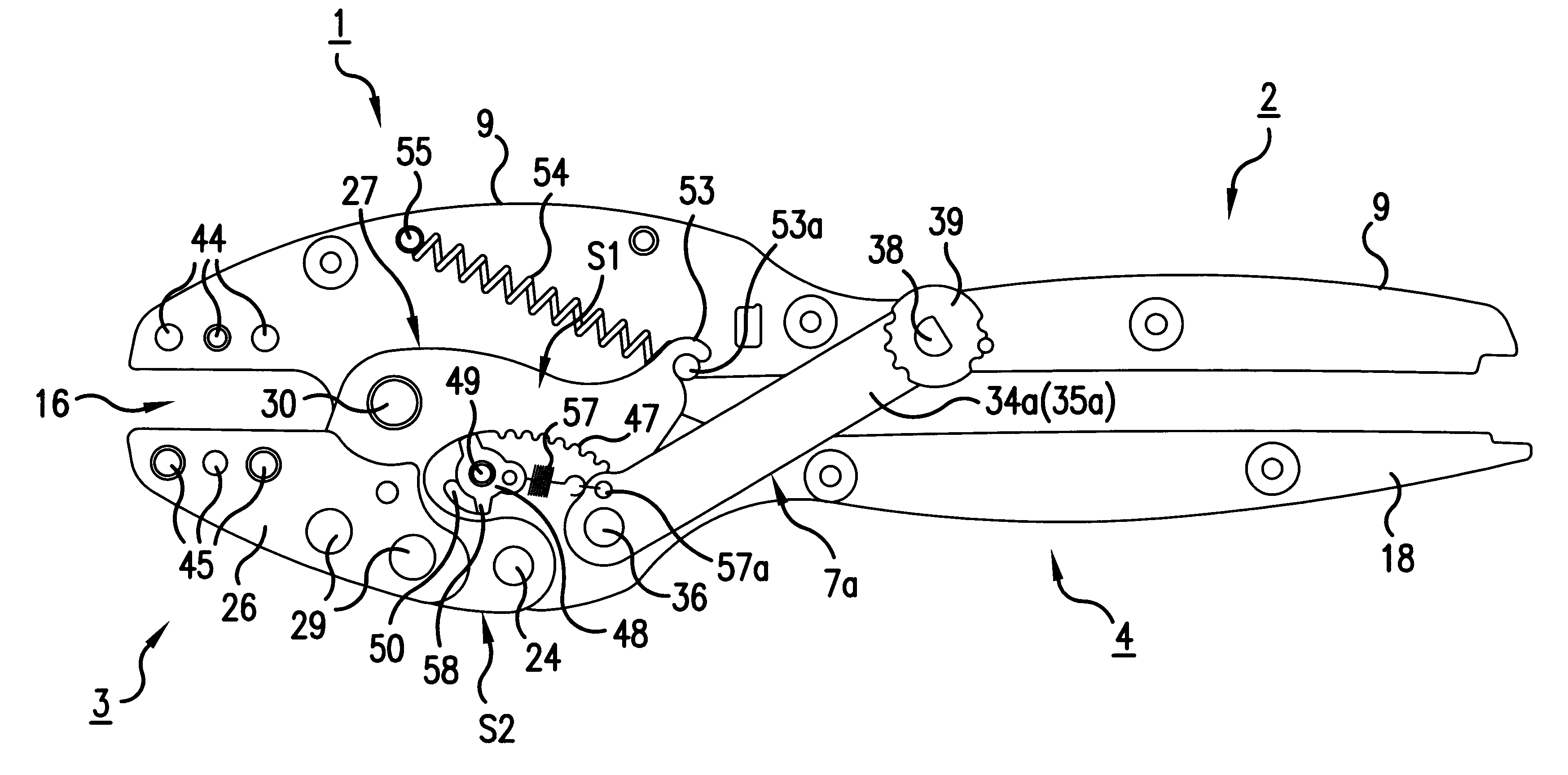
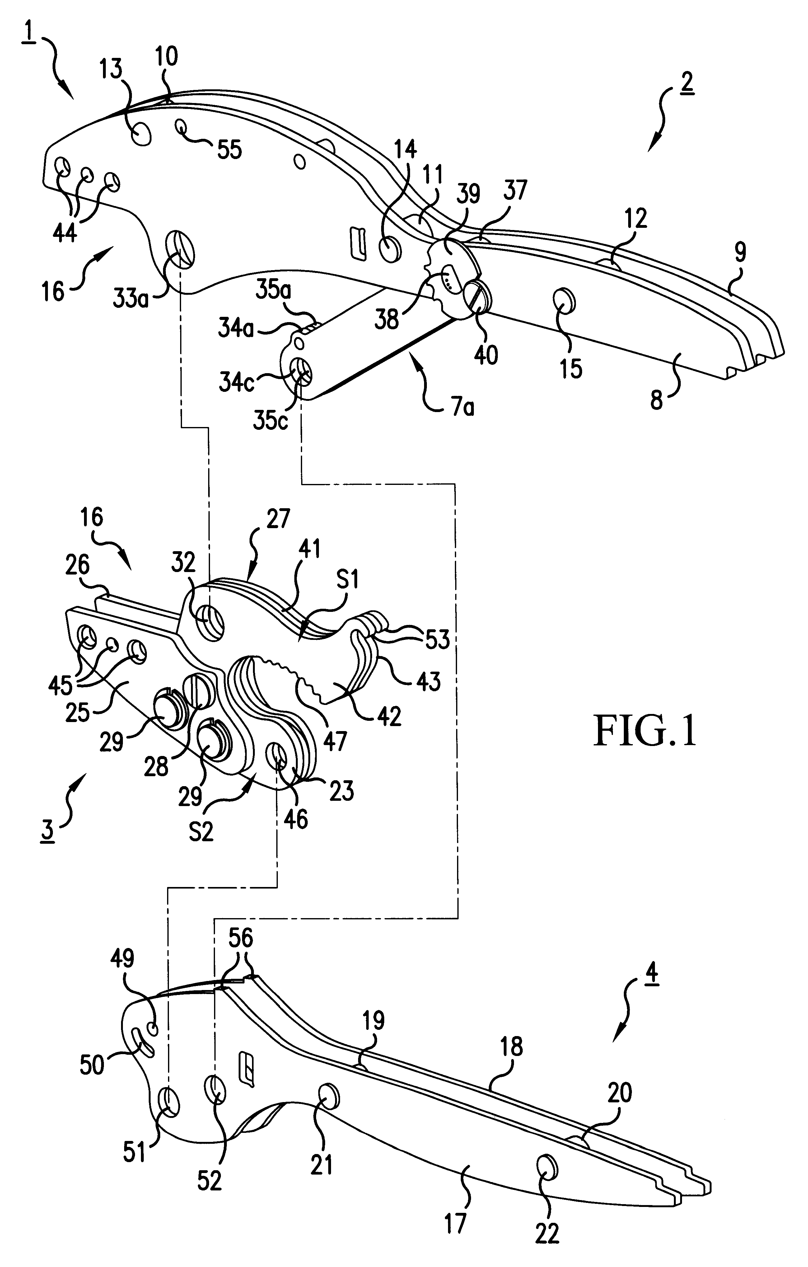
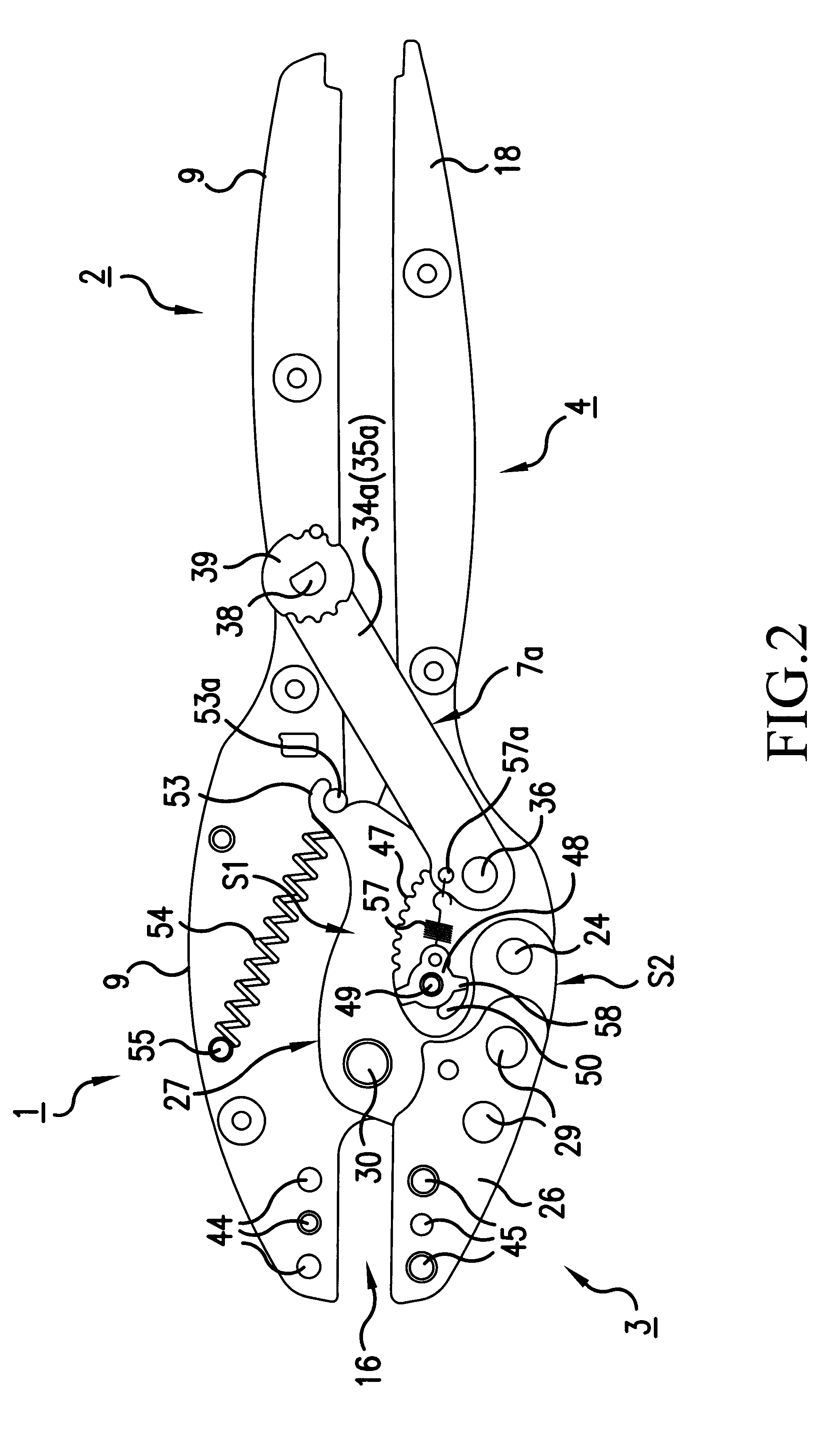
First of all, the exploded illustration in FIG. 1 will be used to explain in more detail the construction of the first exemplary embodiment of the pliers according to the invention;

The pliers according to FIG. 1 essentially comprise a first operating jaw 1;, a first plier handle 2, a second operating jaw 3, a second plier handle 4 and a relatively rigid connecting element 7a.

The first operating jaw l and the first plier handle 2 are connected integrally to one another. This structural unit comprises two mutually parallel plates 8 and 9 which are spaced apart via spacers 10, 11 and 12. Running through the plates 8i and 9 and the spacers 10 , 11 and 12 are bolts 13, 14 and 15 which hold the plates 8 and 9 together. The, plates 8 and 9 are recessed in the front region of the pliers for the purpose of forming a plier mouth 16.

The second plier handle 4 likewise comprises two mutually parallel plates 17 and 18 which are spaced apart from one another via spacers 19 and 20. Running through ...


PUM


Abstract

Pliers with a first operating jaw and a first plier handle fixed thereto, have a second operating jaw mounted pivotably on the first operating jaw, and have a second plier handle which is articulated on a section of the second operating jaw. The section is oriented towards the rear plier end, having a connecting element between the first and second plier handles for the purpose of forming a toggle lever, and has a catch which is arranged at the front end of the second plier handle and is intended for preventing the plier handles from spreading apart before they have reached their closed position, the catch engaging, for this purpose, in a row of teeth. The row of teeth is provided on the second operating jaw.

Description

1. Field of the InventionThe invention relates to pliers.2. Description of the Prior ArtSuch pliers are known already from U.S. Pat. No. 5,842,371. These known pliers contain a first operating jaw and a first plier handle fixed thereto, a second operating jaw mounted pivotably on the first operating jaw, a second plier handle which is provided on a section of the second operating jaw which is oriented towards the rear plier end, a connecting element between the first and second plier handles for the purpose of forming a toggle lever, and a catch which is arranged at the front end of the second plier handle and intended for preventing the plier handles from spreading apart before they have reached their closed position, the catch engaging, for this purpose, in a row of teeth.In the conventional pliers said row of teeth is located at the bottom end of the connecting element, the row of teeth being arranged coaxially with the point of articulation between the connecting element and sec...

Claims


Application Information

Patent Timeline
IPC IPC(8): B25B27/14B25B7/14B25B7/12B25B7/00H01R43/042H01R43/04
CPCB25B7/12B25B7/123H01R43/042B25B27/146B25B7/14
Inventor HEGGEMANN, CHRISTIANHERZOG, ARMINBORNEFELD, THORSTEN
Owner WEIDMULLER INTERFACE GMBH & CO KG
Why Eureka
Try Eureka