Insertion apparatus and insertion method

a technology of insertion apparatus and insertion method, which is applied in the direction of rotary presses, pile separation, printing, etc., can solve the problems of unfavorable loading, large acceleration of products during insertion into the compartment, and a large variation of the spacing between the two dividing walls, so as to facilitate the opening of products and reduce the space requirement (diameter of the apparatus)

Inactive Publication Date: 2012-08-07
FERAG AG
View PDF14 Cites 0 Cited by
  • Summary
  • Abstract
  • Description
  • Claims
  • Application Information

AI Technical Summary

Benefits of technology

[0011]The invention makes it possible to feed the printed products in the direction of the compartments and first of all to convey them further without a significant directional change and therefore without great accelerations by rotation of the circulating system. The aerodynamic resistance of the printed product is reduced by the product being moved further with the folded edge at the front more or less in the direction of the product plane instead of perpendicularly with respect to the latter.
[0013]A further advantage comprises the fact that the diameter of the circulating system for processing products with a predefined maximum format is reduced as a result of the orientation of the compartments which differs from the radial direction in comparison with those systems, in which the compartments are oriented radially, and the system according to the invention can therefore be of more compact configuration than the prior art.
[0014]This design of the circulating system with compartments arranged in an overlapping manner around the rotational center also leads to the products being conveyed within the circulating system in a very compact formation, which makes high conveying rates possible. The formation corresponds substantially to an imbricated formation which runs through a deflection point. The difference from a conventional imbricated formation lies in the fact that dividing walls are arranged between the products within the circulating system. The compartments are wound, as it were, around the rotational axis helically.
[0016]It has been shown that dividing walls which are bent counter to the circulating direction and wind, for example, helically around the rotational axis have advantages, since they facilitate opening of the products. This is because, during fixing of one of the product parts against the bent dividing wall, the folded product normally spreads open without additional measures on account of its inherent rigidity. The opening device can therefore be realized in a simple way by a clamping element which presses one of the product parts against the dividing wall. As an alternative, the opening device can be realized by one or more vacuum nozzles in the dividing wall, as a result of which the adjacent product part is sucked against the dividing wall. Opening devices of this type which fix only one of the product parts can also be used in the case of straight compartment walls.
[0017]A bent dividing wall has the additional advantage that the space requirement (diameter of the apparatus) is reduced in comparison with the case with straight dividing walls.

Problems solved by technology

However, a disadvantage of the known devices is the great accelerations which the products are subjected to during insertion into the compartments on account of the directional change between the feed direction and the direction of conveying in the circulating system.
A further problem arises in the adaptation to different formats: the spacing between the two dividing walls varies to a very pronounced extent with the radius, on which the spacing is measured.
Since the products are normally fixed in the compartments at their edges which lie radially on the outside, shorter products are spread open to a greater extent during opening than longer products and are therefore loaded undesirably in some circumstances.

Method used


Image

  • Insertion apparatus and insertion method
  • Insertion apparatus and insertion method
  • Insertion apparatus and insertion method

Examples


Embodiment Construction

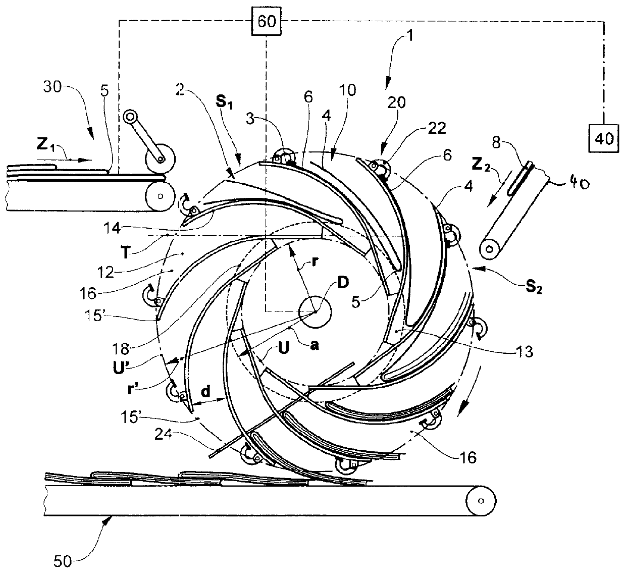
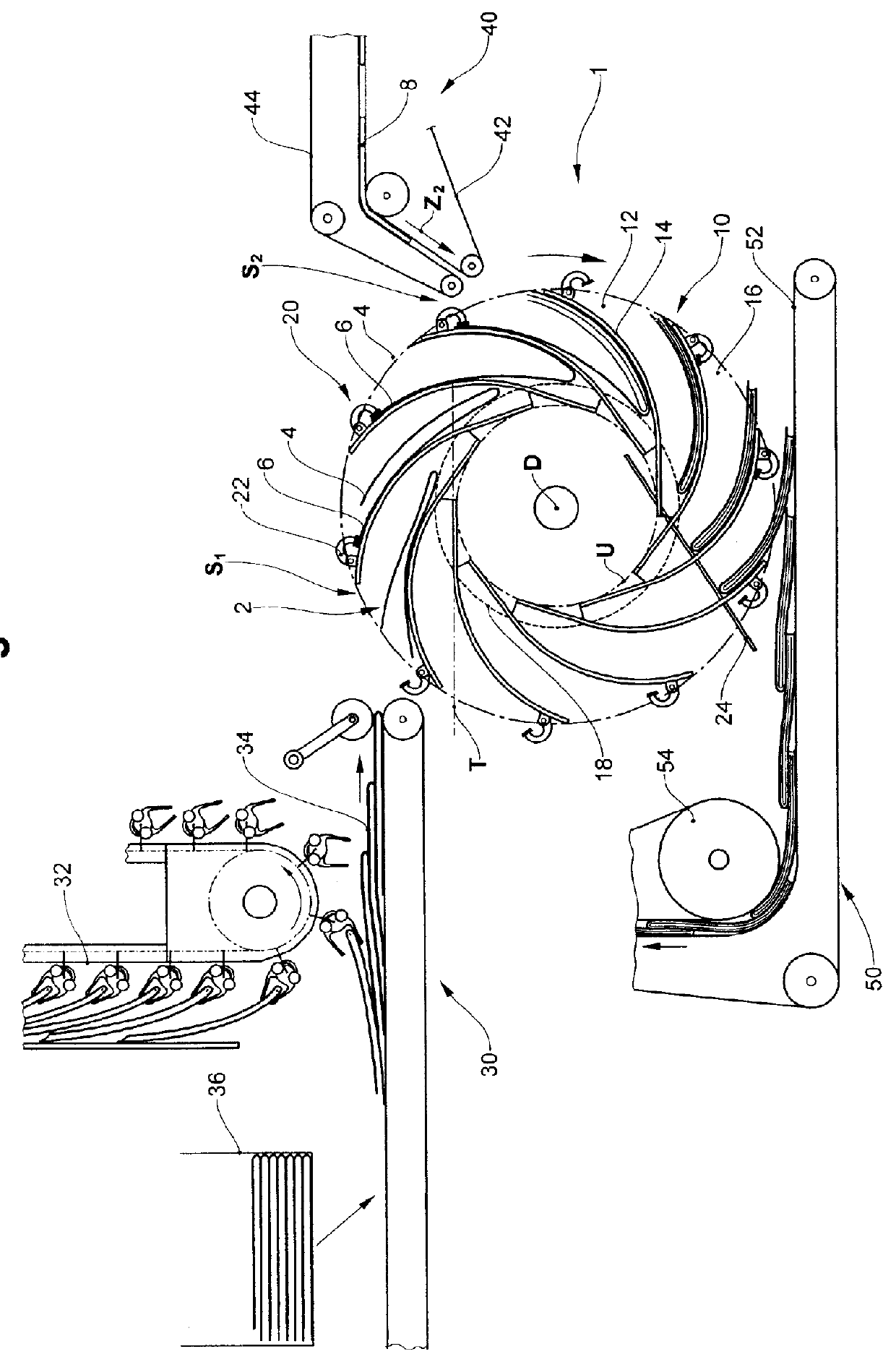
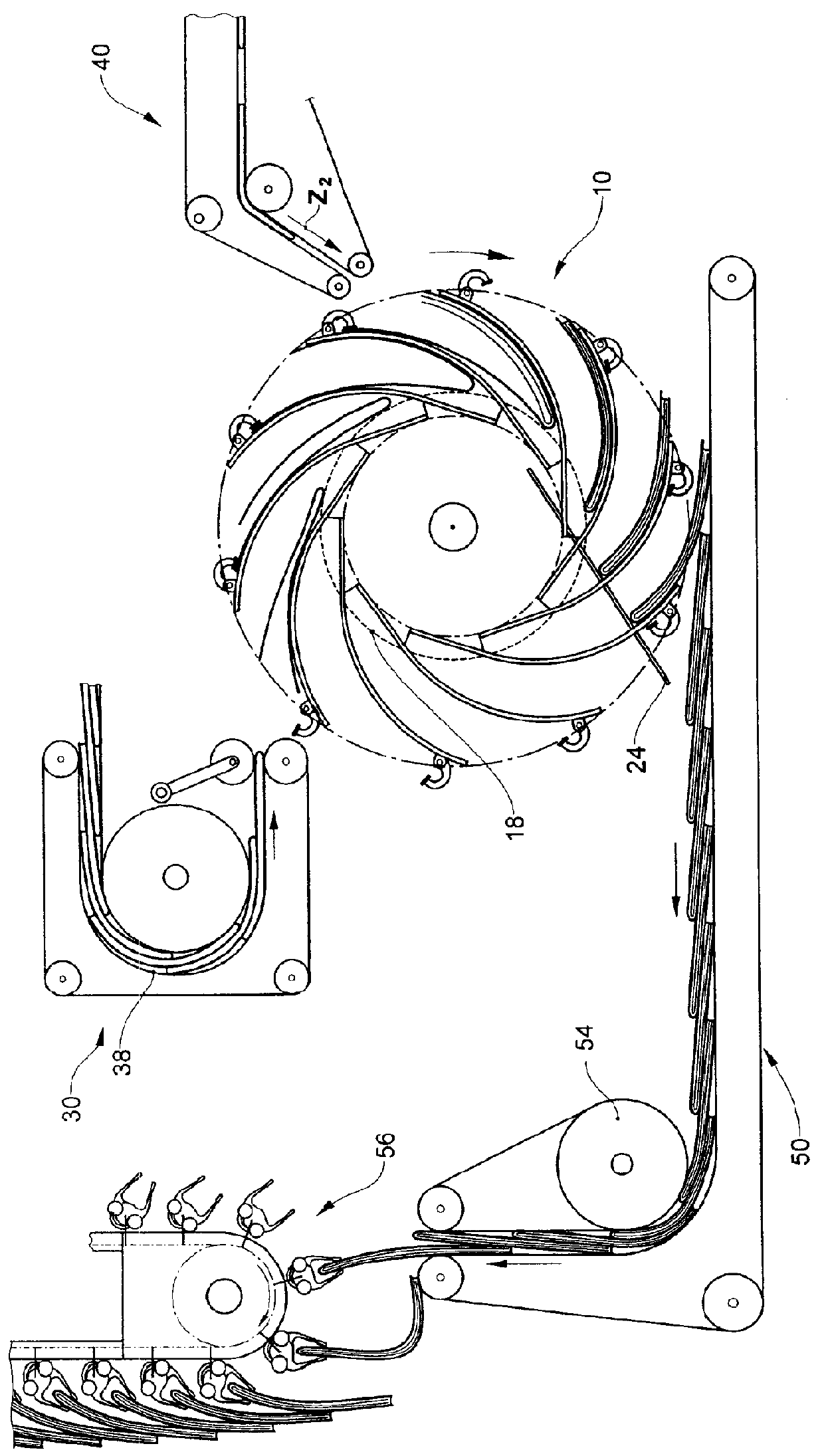
[0026]FIG. 1 shows an inserting apparatus 1 with a circulating system 10 which comprises a plurality of compartments 12. In each case one compartment 12 is formed by two adjacent dividing walls 14. The dividing walls 14 have a continuous 2-dimensional surface or define a 2-dimensional surface. They are mounted on at least one rotational body (not shown here) so as to rotate about a rotational axis D. The dividing walls 14 define receiving pockets for products, which receiving pockets taper from the periphery of the circulating system 10 or the compartment opening 16 toward the compartment base 13.

[0027]As a result of the rotation about the rotational axis D which extends horizontally here, the compartments 12 describe a circular circulating track U with a radius r. In the present case, the circulating track U is denoted by the track of that dividing-wall end 15 which lies at the smallest distance r from the rotational axis D (r>0). If the track of another point on the dividing wall ...


PUM

PropertyMeasurementUnit
angleaaaaaaaaaa
circumferenceaaaaaaaaaa
distanceaaaaaaaaaa

Abstract

An apparatus for, and a method of, inserting flat articles, e.g. printed pre-products or additional products, parts of newspapers, goods samples, leaflets, fliers and other inserts, into folded printed products. Use is made of a rotary system with compartments which run along a closed circular rotary path and are oriented as a tangent or secant to the rotary path (U). This makes it possible for the printed products and the articles to be fed in the direction of rotation, as a result of which the forces acting on the products can be reduced. There are also advantages relating to format adaptation, since the opening angle of the product upon adjustment of the compartment base does not change to such a pronounced extent as is the case with radially oriented compartments.

Description

BACKGROUND OF THE INVENTION[0001]1. Field of Invention[0002]The invention lies in the field of the further processing of printed products and relates, in particular, to an apparatus and a method for inserting flat objects into a folded printed product, for example an envelope. Flat objects of this type are, for example, further printed products, printed preproducts or additional products, parts of newspapers, test samples, brochures, flyers and other inserts. The invention serves, for example, to produce a multiple part printed product.[0003]2. Description of Related Art[0004]In order to insert flat objects between the two product parts of a folded printed product, it is known to transfer the printed products coming from the rotary printing press to a separate apparatus, to hold it in the latter and to open it, to insert the flat objects and to remove the end product produced in this way and to convey it further. The apparatuses which have previously been used for this purpose, for ...

Claims


Application Information

Patent Timeline
Patent Type & Authority Patents(United States)
IPC IPC(8): B65H29/40
CPCB41F13/68B65H5/305B65H29/40B65H39/065B65H5/30B65H2301/431711B65H2301/431715B65H2301/44712B65H2404/655B65H2404/6551B65H2404/6582B65H2406/12B65H2701/1932B65H2220/01B65H2220/02B65H2301/44765B65H29/003
Inventor KELLER, MARTIN
Owner FERAG AG
Why Eureka
Try Eureka