Static electricity neutralizing device and static electricity neutralizing method

Inactive Publication Date: 2016-03-10
ANRITSU CORP
View PDF8 Cites 0 Cited by
  • Summary
  • Abstract
  • Description
  • Claims
  • Application Information

AI Technical Summary

Benefits of technology

[0026]According to the present invention, since the flexible rod-like static electricity neutralizing contact that is erected on the base member installed at the port of the tester is brought into contact with the central conductor and the outer conductor of the coaxial connector of the coaxial cable, it is possible that the static electricity neutralizing device has a more compact configuration than the static electricity neutralizing device in the related art, and a space for installing the static electricity neutralizing device at the tester is decreased when static electricity in the charged coaxial cable is neutralized.
[0027]In addition, when the coaxial connector of the coaxial cable is connected to adapters which are connected to the coaxial connector of the ports, after the ground spring that is disposed in the base member by being inserted around the adapter is initially brought into conta

Problems solved by technology

In the particular case of the tester using high-frequency signals that are susceptible to stati

Method used


Image

  • Static electricity neutralizing device and static electricity neutralizing method
  • Static electricity neutralizing device and static electricity neutralizing method
  • Static electricity neutralizing device and static electricity neutralizing method

Examples


first embodiment

[Entire Configuration of Static Electricity Neutralizing Device in First Embodiment]

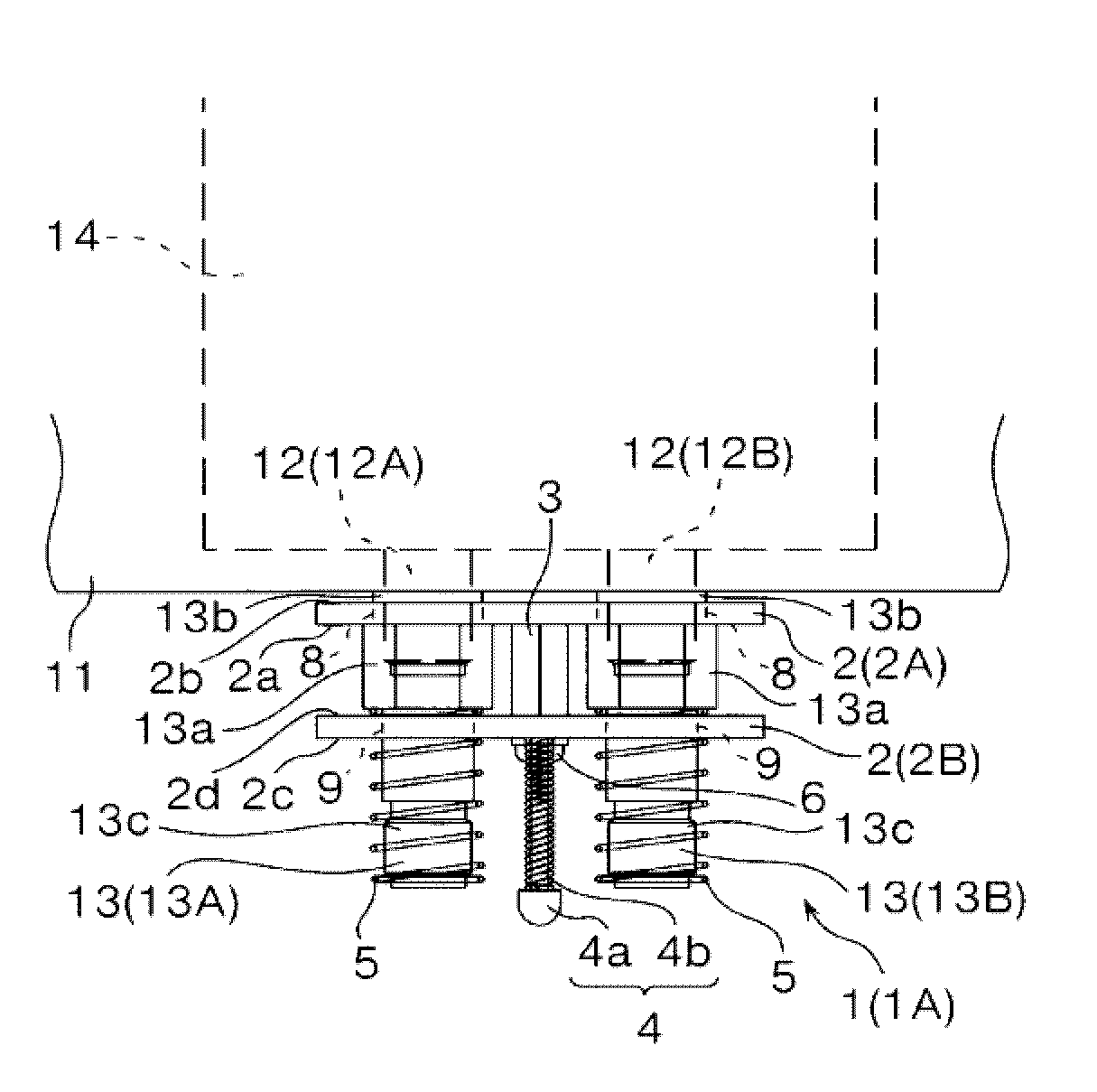
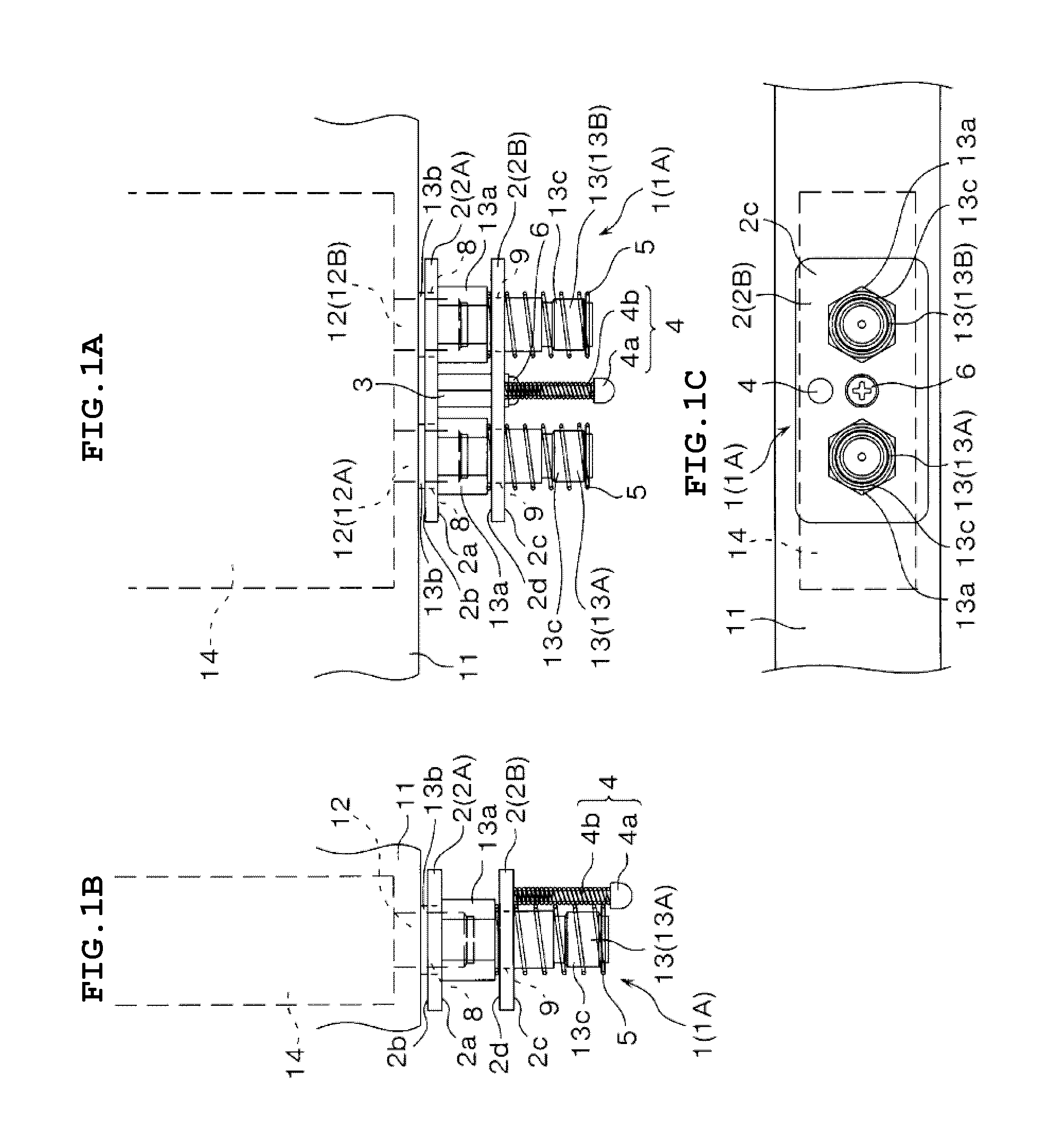
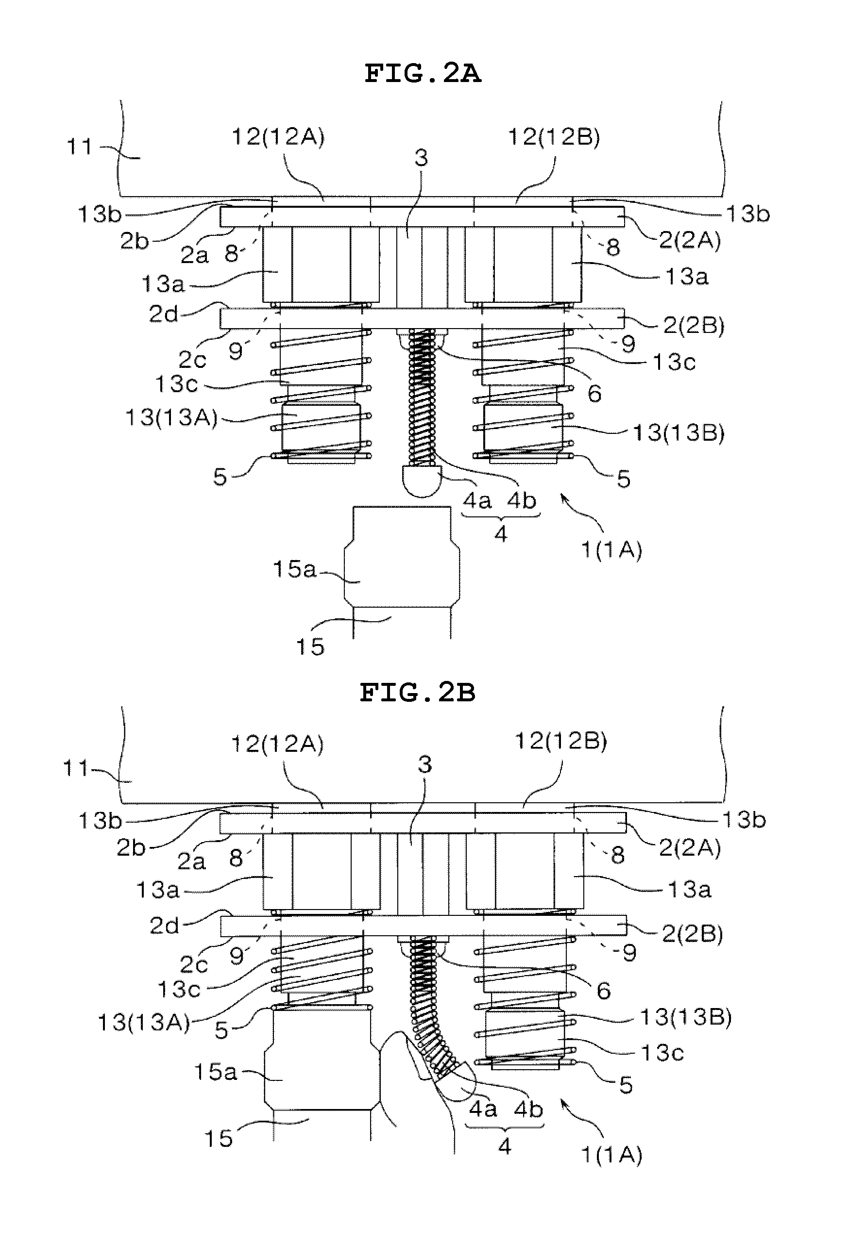
[0042]A static electricity neutralizing device 1A (1) is schematically configured as provided with a base member 2, a support member 3, a static electricity neutralizing contact 4, a ground spring 5, and fixing means 6 as illustrated in FIGS. 1A-1C.

[0043]The base member 2 is a member intended to be fixedly installed at the adapter 13 (13A and 13B) of the port (coaxial connector 12) of the testing unit 11 and is configured by a first base member 2A and a second base member 2B that are held substantially parallel to each other at a predetermined interval. The first base member 2A is configured by a conductive rectangular metal plate member. Two insertion holes 8 are formed in the first base member 2A. The insertion holes 8 correspond to the exterior of the first connector unit 13b of the adapter 13 (13A and 13B) that is connected to the coaxial connector 12. The insertion holes 8 are formed at two lef...

second embodiment

[Entire Configuration of Static Electricity Neutralizing Device in Second Embodiment]

[0056]A static electricity neutralizing device 1B (1) is schematically configured as provided with a base member 2′, the static electricity neutralizing contact 4, the ground spring 5, and the fixing means 6 as illustrated in FIGS. 3A-3C.

[0057]The static electricity neutralizing device 1B in the second embodiment is different from the static electricity neutralizing device 1A in the first embodiment in that the direction of interposition of the adapter 13 is different when the static electricity neutralizing device 1B is fixedly installed at the adapter 13 (13A and 13B) of the testing unit 11. Other configurations are substantially the same, and substantially the same configurations will be described with the same reference sign.

[0058]The base member 2′ is a member intended to be fixedly installed at the adapter 13 (13A and 13B) of the port (coaxial connector 12) of the testing unit 11 and is config...


PUM


Abstract

To neutralize static electricity in a charged coaxial cable with a decreased installation space. The first base member 2A and the second base member 2B are installed at the adapter 13 in order to interpose a box nut 13a of the adapter 13 therebetween and are fixed by fixing means 6. A flexible rod-like static electricity neutralizing contact 4 is erected on the second base member 2B parallel to the adapter 13. The static electricity neutralizing contact 4 is brought into contact with a central conductor and an outer conductor of a coaxial connector 15a before the coaxial connector 15a of a coaxial cable 15 is connected to the adapter 13, and static electricity in the charged coaxial cable 15 is neutralized.

Description

TECHNICAL FIELD[0001]The present invention relates to a static electricity neutralizing device and a static electricity neutralizing method that are intended, when various tests are performed for a device under test (DUT) by using an electronic device such as a tester, to prevent damage to the tester due to static electricity in a charged coaxial cable which connects the tester to the device under test.BACKGROUND ART[0002]One type of testers is known to have a function of performing various tests for a device under test by using a specific signaling scheme that is based on various wired system communication protocols such as synchronous digital hierarchy (SDH), plesiochronous digital hierarchy (PDH), optical transport network (OTN), and Ethernet (registered trademark). This type of testers is configured as one device provided with multiple pieces of testing hardware and testing applications. The tester tests a device under test with individual testing applications controlling predet...

Claims


Application Information

Patent Timeline
IPC IPC(8): G01R1/18G01R31/02
CPCG01R31/021G01R1/18H01R13/6485H01R13/24
Inventor HAYAKAWA, SATOSHI
Owner ANRITSU CORP
Why Eureka
Try Eureka