
Apparatus for producing printing plates having movable journal for axial removal of plate

a technology of printing plate and axial removal, which is applied in the direction of photomechanical apparatus, printing form reproduction, instruments, etc., can solve the problems of occupying a great deal of space, cumbersome, time-consuming and cumbersome changes

Inactive Publication Date: 2003-02-18
MANROLANAD AG
View PDF16 Cites 18 Cited by
  • Summary
  • Abstract
  • Description
  • Claims
  • Application Information

AI Technical Summary

Problems solved by technology

This takes up a great deal of space, in particular when removing a sleeve-like printing plate.
In addition, making the change is time consuming and cumbersome.

Method used


Image

  • Apparatus for producing printing plates having movable journal for axial removal of plate
  • Apparatus for producing printing plates having movable journal for axial removal of plate
  • Apparatus for producing printing plates having movable journal for axial removal of plate

Examples


Embodiment Construction

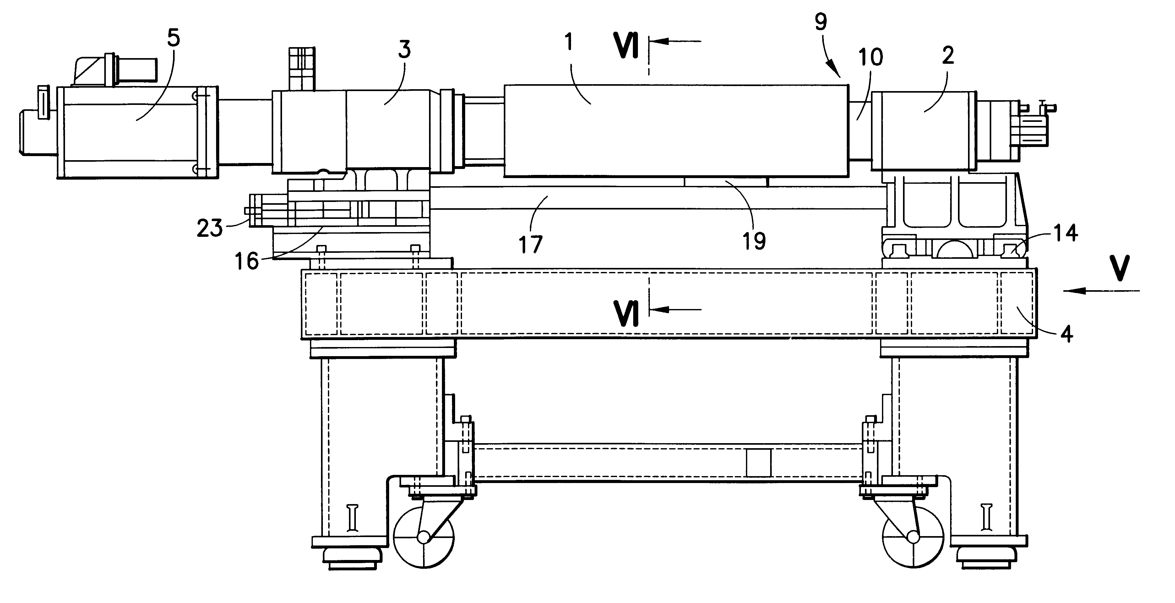
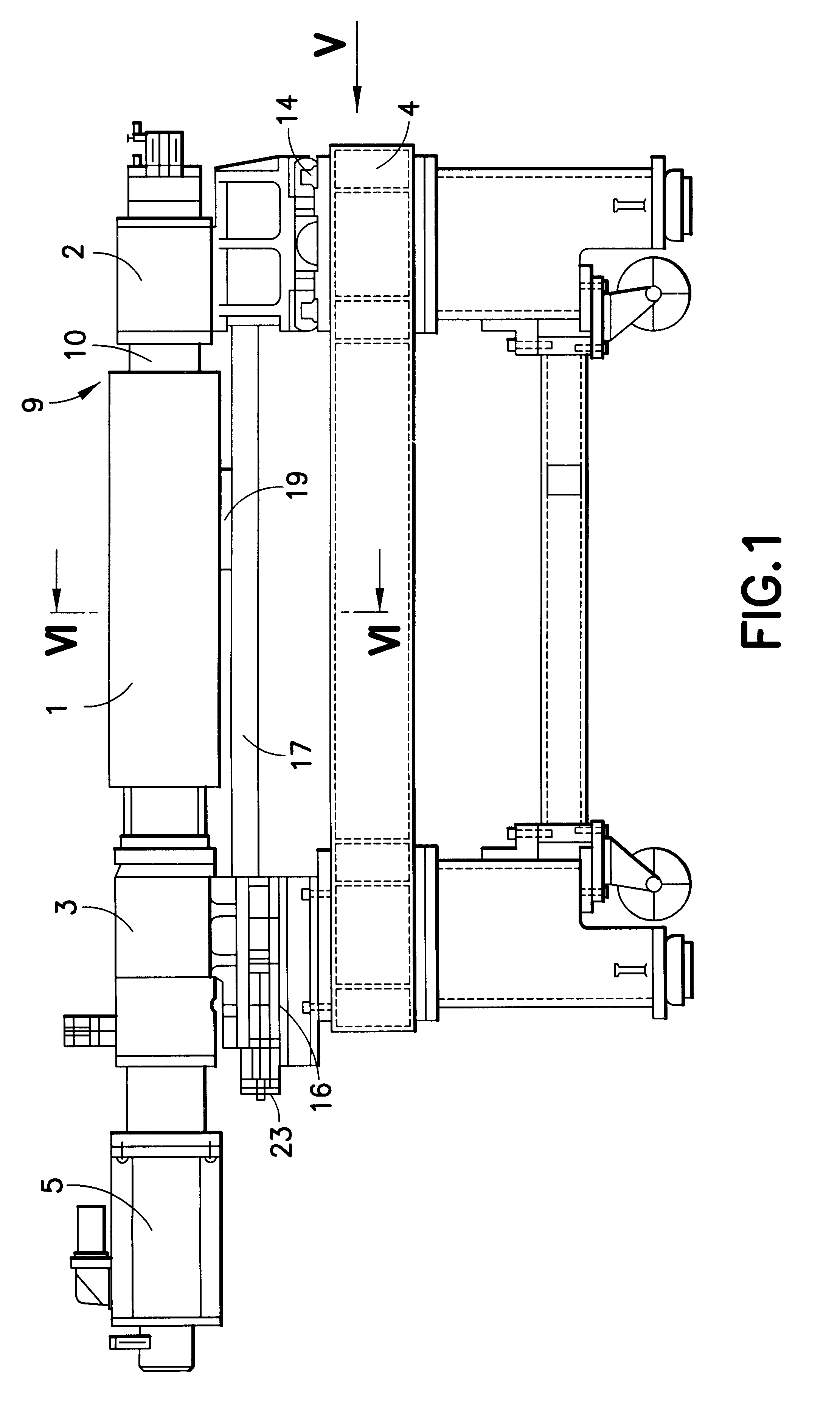
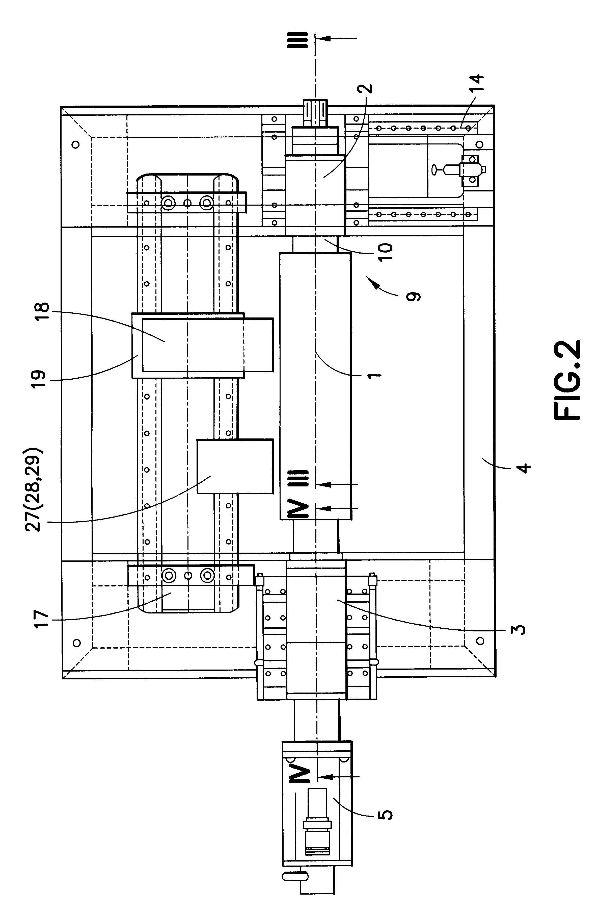
Referring to FIG. 1, an apparatus according to the present invention is shown. The apparatus comprises a supporting cylinder 1, which is mounted at both ends in a first and second mounting 2, 3. Both mountings 2, 3 are arranged on a frame 4. The second mounting in this embodiment is designed as a fixed bearing and the first mounting 2 is designed as a loose bearing. As a result of this mounting configuration, the bearings are protected and there is no transmission of stresses to the frame. The supporting cylinder 1 is driven by a motor 5 which, for this purpose, is flange mounted to the housing 6 of the second mounting 3 (shown in FIG. 4). The motor 5 is arranged coaxially with the longitudinal axis (axis of rotation) of the supporting cylinder 1. The output shaft of the motor 5 can advantageously be connected, by means of a coupling 7, to a second journal 8 of the supporting cylinder 1. Alternatively, the supporting cylinder can also be driven by a flexible drive via a motor flange...


PUM

PropertyMeasurementUnit
flexibleaaaaaaaaaa
diameteraaaaaaaaaa
external diameteraaaaaaaaaa

Abstract

An apparatus for producing printing plates on a supporting cylinder is provided. Mountings arranged on a frame accommodate a blank printing plate arranged on a supporting cylinder. The supporting cylinder is driven by a motor. The apparatus allows the supporting cylinder to be exposed at an end opposite the motor by its journal together with the mounting accommodating the journal. Thus, the supporting cylinder is capable of being moved away from the frame at one end, which makes it possible to draw the printing plate axially off the supporting cylinder. The apparatus can be used to produce a variety of printing plates, including: a relief printing plate, an offset printing plate, a sleeve-like printing plate, and a gravure printing plate.

Description

1. Field of the InventionThe present invention relates to an apparatus for producing printing plates.2. Description of the Related ArtAn apparatus is known in which a cylinder for receiving an image is clamped into tail stocks of a guide bed. A gravure printing plate is engraved in this cylinder by means of an image setting device in the form of an electronically controlled gauge. In order to remove the cylinder, at least one tail stock has to be moved sideways. This takes up a great deal of space, in particular when removing a sleeve-like printing plate. In addition, making the change is time consuming and cumbersome.The object of the present invention is to provide an economical apparatus for making a printing plate where the printing plate can be changed in a small space. The present invention is particularly useful for changing sleeve-like printing plates.According to the present invention, the apparatus includes a frame, two mounting elements, a supporting cylinder, two journal...

Claims


Application Information

Patent Timeline
Patent Type & Authority Patents(United States)
IPC IPC(8): B41C1/10B41C1/00B41F27/00B41C1/18B41F27/14B41N10/00G03F1/00G03F7/24
CPCB41C1/1083B41C1/00Y10S101/36
Inventor PETERSEN, GODBERGOTTLING, JOSEFHARTMANN, THOMAS
Owner MANROLANAD AG
Learn More