Resin composition for laser engraving, relief printing plate precursor for laser engraving and method for producing the same, and relief printing plate and method for making the same
a technology of laser engraving and resin composition, which is applied in the field of resin composition for laser engraving, can solve the problems of difficult scrap removal and deterioration of the water resistance of the plate itself, and achieve the effect of improving the water resistance of the plate and reducing the cost of production
- Summary
- Abstract
- Description
- Claims
- Application Information
AI Technical Summary
Problems solved by technology
Method used
Image
Examples
example 1
[0356]1. Preparation of Coating Liquid for Forming Relief Forming Layer
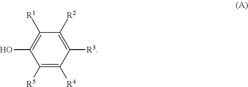
[0357]In a three necked flask equipped with a stirring blade and a cooling tube, 50 parts by mass of PVB “DENKA BUTYRAL #3000-2” (trade name, manufactured by Denki Kagaku Kogyo K.K.; polyvinyl butyral; weight average molecular weight (Mw)=90,000) as the binder polymer (B), 36 parts by mass of the above-described exemplified compound A-1 (manufactured by Tokyo Chemical Industry Co., Ltd.; methyl 4-hydroxybenzoate) as the phenol derivative (A), and 47 parts by mass of propylene glycol monomethyl ether acetate as the solvent were placed, and the mixture was heated while stirring at 70° C. for 120 minutes to dissolve the polymer.
[0358]Thereafter, the resulting solution was cooled to 40° C., and to this solution, 1 part by mass of KETJENBLACK EC600JD (trade name, manufactured by Lion Corporation; carbon black) as the photothermal conversion agent (D) was added, and the mixture was stirred for 30 minutes.
[0359]Then, to...
example 28
[0377]Preparation of a relief printing plate precursor for laser engraving was conducted in a manner substantially similar to that in Example 1, except that a coating liquid for forming a relief forming layer was prepared by replacing the crosslinking agent (C) in the “1. Preparation of Coating Liquid for Forming Relief Forming Layer” in Example 1 with 3,3′,4,4′-diphenyl sulfone tetracarboxylic dianhydride (manufactured by Tokyo Chemical Industry Co., Ltd.; the above-described specific example (6)). Thereafter, a relief printing plate 28 was prepared from the resulting relief printing plate precursor for laser engraving.
example 29
[0378]Preparation of a relief printing plate precursor for laser engraving was conducted in a manner substantially similar to that in Example 1, except that a coating liquid for forming a relief forming layer was prepared by replacing the crosslinking agent (C) in the “1. Preparation of Coating Liquid for Forming Relief Forming Layer” in Example 1 with 2,4-tolylene diisocyanate (manufactured by Tokyo Chemical Industry Co., Ltd.). Thereafter, a relief printing plate 29 was prepared from the resulting relief printing plate precursor for laser engraving.
PUM
| Property | Measurement | Unit |
|---|---|---|
| Tg | aaaaa | aaaaa |
| wavelength | aaaaa | aaaaa |
| wavelength | aaaaa | aaaaa |
Abstract
Description
Claims
Application Information
 - R&D
- Intellectual Property
- Life Sciences
- Materials
- Tech Scout
- Unparalleled Data Quality
- Higher Quality Content
- 60% Fewer Hallucinations
Browse by: Latest US Patents, China's latest patents, Technical Efficacy Thesaurus, Application Domain, Technology Topic, Popular Technical Reports.
© 2025 PatSnap. All rights reserved.Legal|Privacy policy|Modern Slavery Act Transparency Statement|Sitemap|About US| Contact US: help@patsnap.com


