Lock, in particular for motor vehicle doors

a technology for motor vehicles and locks, applied in the field of motor vehicle doors, can solve the problems of not being able to guarantee that the actuator can assume its specific position or retain it for a sufficiently long period of time, and the door paneling is not longer accessible,

Inactive Publication Date: 2003-02-25
VDO ADOLF SCHINDLING AG
View PDF21 Cites 85 Cited by
  • Summary
  • Abstract
  • Description
  • Claims
  • Application Information

AI Technical Summary

Benefits of technology

to provide a lock having an additional mechanical transmission device for the unlocking which, in the event of a malfunction, in particular without electric energy or upon failure of the electric current supply, can be effectively actuated.
As a further development of the invention, the lever (3) has a guide, a pusher connected with the Bowden cables being slidably mounted in a slide block (3.13) in this guide. Furthermore, the pusher is formed of two parts, each part being connected with the Bowden cable (3.4, 3.10). There is thus available a construction which makes it possible to actuate a lever from two different places independently of each other.

Problems solved by technology

These arrangements have the disadvantage that in the event of a failure of electrical or electronic parts (for instance of the switches) or of the voltage supply, it must be seen to it that the load-free actuator moves into its active position and is held, for instance, in this active position by self-locking, i.e. the movable setting member must, in the event of a malfunction, be moved by electric energy into to a specific position in order, by actuation of the manipulator (door inside handle or door outside handle) over a larger region of displacement than the electric unlocking, to effect a mechanical opening of the doors.
However, if there is no electrical energy (for instance, in the event of failure of the battery due to cold or after an accident, or if the terminals of the battery have become disconnected upon stay in a workshop or during transportation of the vehicle) there is no assurance that the actuator can assume its specific position or retain it for a sufficiently long period of time.
This serves to provide mechanical redundancy, and the problems related therewith, such as sufficient availability in time of the required energy cannot occur.
Such inner safety buttons are known per se and are, when the door is closed (particularly in an anti-theft position of the lock), so sunk in the paneling of the door that they are not longer accessible.

Method used


Image

  • Lock, in particular for motor vehicle doors
  • Lock, in particular for motor vehicle doors
  • Lock, in particular for motor vehicle doors

Examples


Embodiment Construction

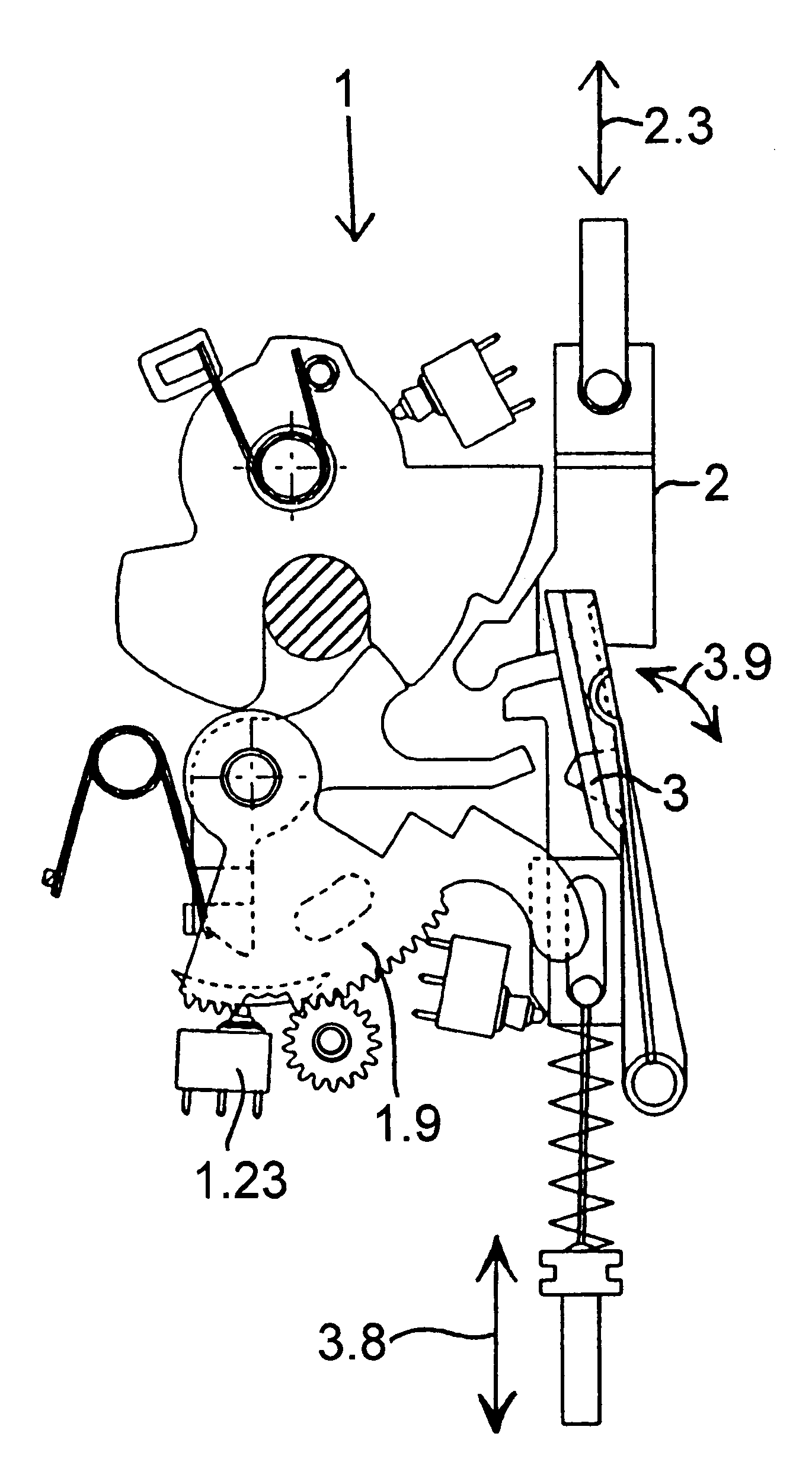
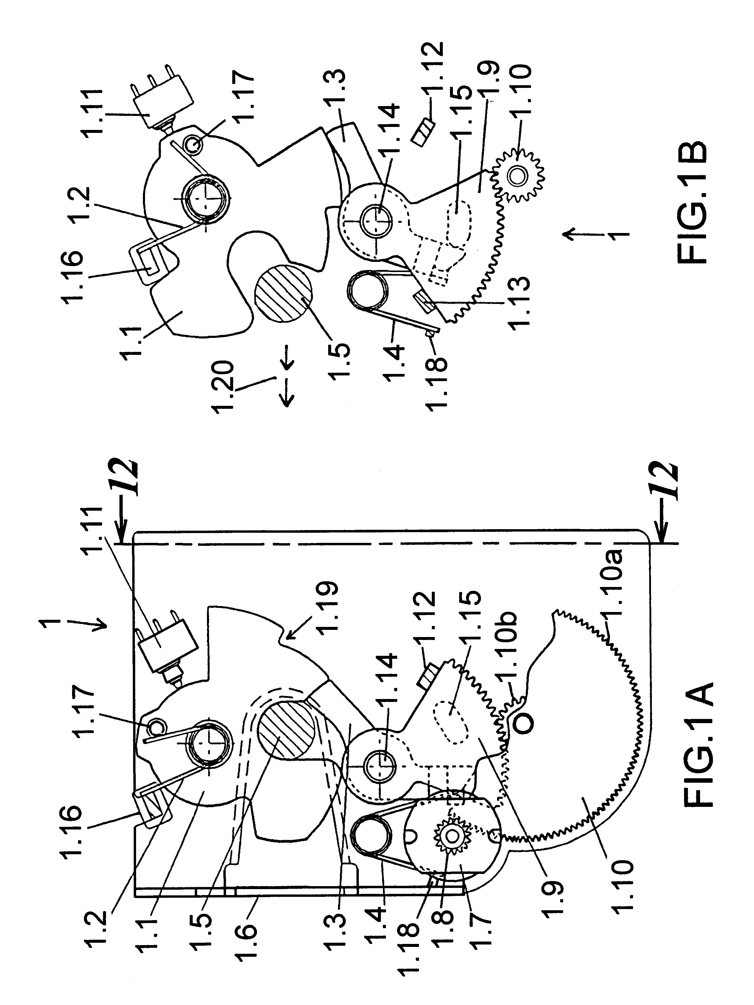
A lock 1, shown in FIGS. 1A and 1B, has a rotary latch 1.1 which acts against a rotary-latch spring 1.2. The rotary latch 1.1 is held in this figure in the locked position shown by a pawl 1.3 which acts against a pawl spring 1.4. The U-shaped rotary latch 1.1 by its two arms surrounds a locking wedge 1.5 and thus holds for instance a car door in known manner in its closed position. The above-indicated parts as well as the following parts are mounted on a lock plate 1.6, in which connection this lock plate 1.6 can also represent a housing which can be easily, simply and in space-saving manner mounted, for instance, within the door of the motor vehicle.

The setting device is developed as an electric motor 1.7 on the output shaft of which there is a pinon 1.8 which is mechanically coupled to a toothed segment 1.9 which then acts on the pawl 1.3. In FIG. 1A, it is shown that the toothed segment 1.9 acting on the pawl 1.3 is connected via a toothed segment 1.10 to the pinion 1.8. In that ...


PUM


Abstract

A lock suitable for use in a motor vehicle door has a rotary latch, a locking wedge, a pawl, a setting device, and a transmission device wherein the rotary latch cooperates with the locking wedge to be locked in a locking position by the pawl. Upon actuation of a manipulator, the setting device brings the pawl electrically at least into one opening position. The transmission device brings the pawl into its opening position by actuation of the manipulator over a displacement range which is greater than a displacement range of an electric unlocking.

Description

FIELD AND BACKGROUND OF THE INVENTIONThe present invention relates to a lock, particularly a lock for motor vehicle doors, which is electrically operable and has an emergency opening.A lock (1) is known, in particular for motor vehicle doors, which has a rotary latch (1.1) which cooperates with a locking wedge (1.5) or the like and can be locked in a locking position by a pawl (1.3), in which connection, upon actuation of a manipulator (for instance, door inside handle or door outside handle), a setting device brings the pawl (1.3) electrically at least into one opening position. The lock includes a transmission device which brings the pawl (1.3) into its opening position by actuation of the manipulator over a displacement range which is greater than an electric unlocking.Such a lock is known from European Patent Application 0 589 158 A1, which has a rotary latch which cooperates with a closure bolt or the like and is locked in a locking position by a pawl. A manipulator is connecte...

Claims


Application Information

Patent Timeline
Patent Type & Authority Patents(United States)
IPC IPC(8): E05B65/20E05B65/12E05B77/12E05B77/26E05B77/28E05B77/30E05B81/14E05B83/36
CPCE05B77/28E05B77/26E05B81/14E05B77/12E05B77/30E05B83/36Y10T70/7102Y10T70/5973Y10T70/7062Y10T292/1082Y10T70/5978Y10T70/7107
Inventor BAUKHOLT, THEORATHMANN, KLAUS-PETERLUBBEN, JENSPETZOLD, SVEN
Owner VDO ADOLF SCHINDLING AG
Why Eureka
Try Eureka