
Method and Apparatus for Spray Paint Marking

Inactive Publication Date: 2005-11-03
SCHMELING GLENN E
View PDF15 Cites 17 Cited by
  • Summary
  • Abstract
  • Description
  • Claims
  • Application Information

AI Technical Summary

Benefits of technology

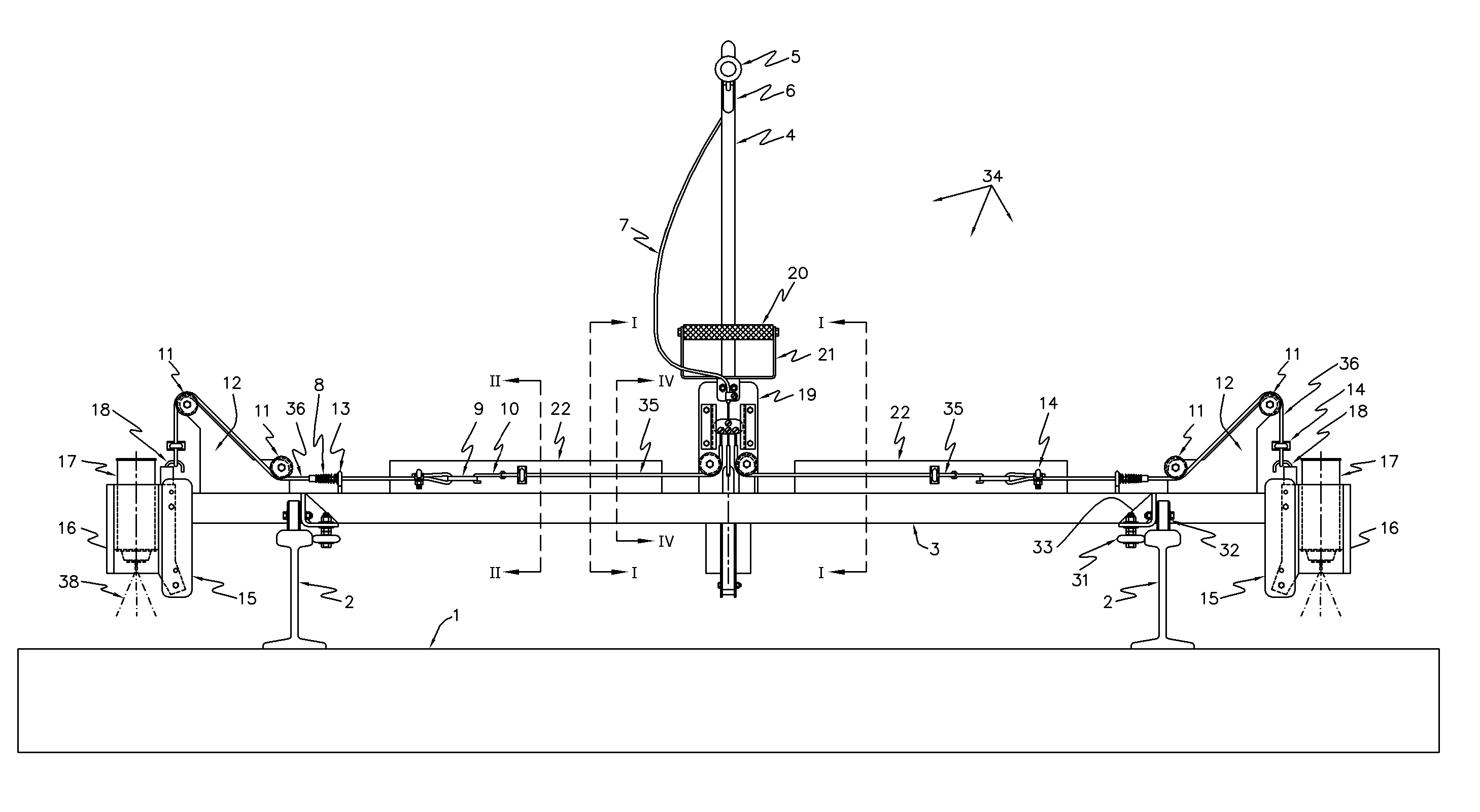
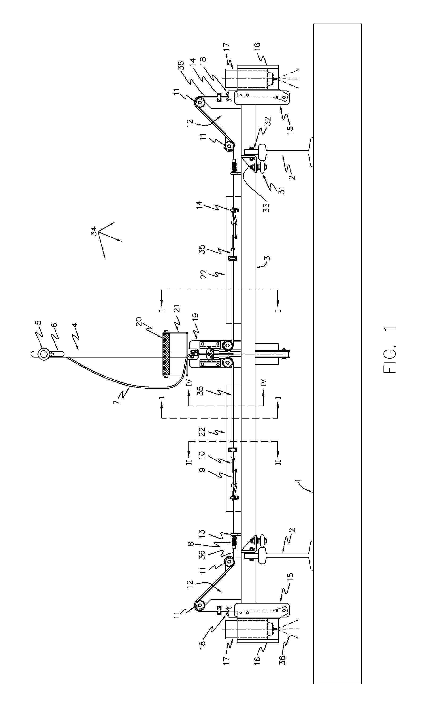
[0019] The present invention provides for a method and apparatus which overcomes the limitations described above by providing a lightweight mobile spray painting device in which a plurality of spray paint cans are selectively mounted on both ends and / or in the center of the apparatus allowing the operator to selectively mark the exposed surfaces of a railroad tie in a multitude of locations at the same time. In the alternative, a single spray paint can, or multiple spray paint cans, can be mounted underneath the main frame of the apparatus, in a horizontal position, to be used selectively to spray paint mark a railroad track above a railroad tie chosen for replacement.
[0024] In this manner, the operator and the rest of the gang crew can be assured that all of the appropriate railroad ties are plainly marked at both ends of the railroad tie and in any other railroad tie location so desired by the railroad gang crew. This means of simultaneous multiple marking of the railroad ties reduces the time and effort required by the operator to mark both ends of the railroad ties. This device also allows the rest of the railroad gang to perform their job functions with less errors and mistakes thereby saving lost time, improving productivity and reducing costs.
[0025] The present invention provides for a reasonably accurate perpendicular relationship to the railroad track and a parallel relationship to the railroad ties with the use of a plurality of rollers attached to a roller bracket that is attached to the frame of the present invention. The present invention also allows for the adjustment of the spray paint can triggering mechanism to assure that the spray paint cans are actuated effectively when the invention is utilized.
[0026] The optional spray paint can trays provide an easy and safe means for carrying addition spray paint cans and for collecting the spent cans for proper disposal later while the operator is using this device.
[0027] The present invention also allows for the easy movement of the device through the use of the push handle and the easy removal of the push handle to allow for the compact storage and reduced damage to the apparatus during transportation to and from the work site. The carrying handle provides for an easy and balanced means for lifting and carrying the device where needed.
[0028] The design of the shaped spray paint nozzle provides an apparatus and a means for shaping the spray paint exiting from the spray paint cans into a variety of spray paint patterns. Depending upon the shape of the spray paint nozzle, the resulting spray paint mark could be something other than a simple spray painted circle. For example, the resulting spray paint could be a long line, a circle with a hole in it, an “X”, or any other shape suitable to a nozzle design. The spray paint nozzle design can also include a spray paint nozzle clip which allows for the positioning of the spray paint nozzle in any orientation desired by the user. The spray paint nozzle designs have other applications than just for the marking of railroad ties and those designs and uses would be apparent to anyone skilled in the art.

Problems solved by technology

A significant disadvantage of wooden railroad ties is that they are susceptible to deterioration and decay.
Since wood is a cellulose material, it is subject to damage from fungus, decay, termite infestation, the stress and strain of railroad usage and exposure to the elements in unprotected outdoor environments.
Railroad ties are particularly susceptible to damage and deterioration in the railroad tie ends and in the connection areas adjacent to each end where the tracks are attached to the railroad ties.
Under railroad traffic, these connection areas are naturally subjected to more stress than any other part of the railroad tie, whereby the railroad ties tend to experience the greatest amount of wear.
Moreover, the plates tend to collect and retain moisture, thereby exacerbating deterioration at the railroad tie ends.
Although preservatives are commonly applied to structural wooden members that will be exposed to the natural elements, the protection provided by such preservatives tends to lessen over time because the preservatives are susceptible to the deteriorating effects of sunlight, precipitation, freeze-thaw cycles, and so forth.
Thus, the useful service life of a railroad tie is generally limited.
However, at some point in the life of the railroad tie, it becomes decayed or damaged to the point that there is no other alternative but to remove the railroad tie and replace it with a new railroad tie.
While this process and procedure ultimately gets the older deteriorated ties replaced, there are some errors, problems and inefficiencies that occur in the existing procedure.
When this occurs, there are multiple consequences to the railroad gang, railroad track and the railroad company.
This typically causes a delay of about ten minutes for the majority of the 50 to 70 person crew each time the spike removal crew is called back.
The other possibility, if the spikes have not been removed on one side of the railroad tie, is that the railroad tie removal crew does not see the existing spikes and attempts to remove the railroad tie.
This can cause the railroad tie to break in half and / or cause the railroad track to twist or warp.
Depending upon the condition of the railroad track, this can cause significant additional delays to the entire crew.
If the railroad tie removal crew sees that the spikes are still in the railroad tie, they stop all work and call back the spike extraction crew to remove the spikes thus causing additional delays in the progress of work.
If the railroad tie removal crew does not see that the spikes are still in place at both ends of the railroad tie and try to remove the railroad tie, significant damage can occur.
The only difference to the damage is in the magnitude of the damage to the railroad track if the railroad tie removal crew attempts to remove the railroad tie when the spikes are still in both ends of the railroad tie.
Obviously, there is a greater possibility of more extensive damage to the railroad track, railroad bed, the removal equipment and to the safety of the railroad gang members.
Unfortunately, the job of marking the railroad track and ties is somewhat monotonous and boring, further leading to more errors and missed markings of railroad ties needing replacement.

Method used


Image

  • Method and Apparatus for Spray Paint Marking
  • Method and Apparatus for Spray Paint Marking
  • Method and Apparatus for Spray Paint Marking

Examples


Embodiment Construction

[0043] Detailed embodiments of the present invention are disclosed herein as illustrated in the drawings; however it is to be understood that the disclosed embodiments are merely exemplary of the invention, which may be embodied in various forms. In addition, although the invention is described and explained by the use of the inventions application to railroad tracks and railroad ties, there is no intent to limit the invention to the embodiment or embodiments disclosed therein. On the contrary, the intent is to include all alternatives, modifications and equivalents included within the scope and spirit of the inventions as defined by the appended claims.

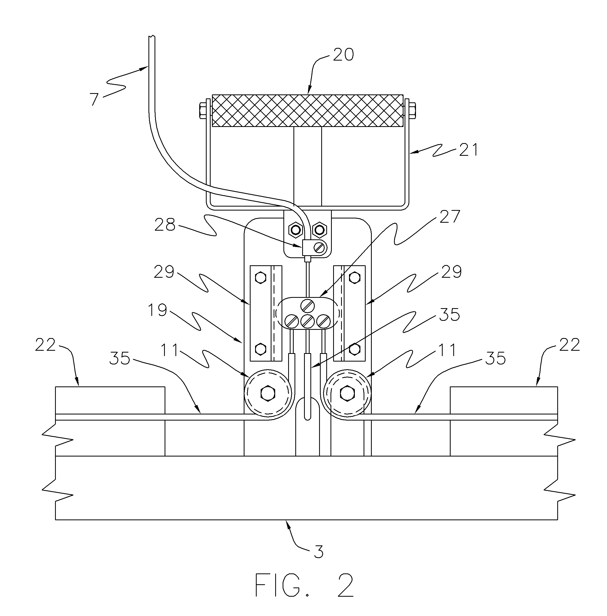
[0044] Referring first to FIG. 1, the frontal view of a multiple nozzle paint spray apparatus 34 is generally shown. As will be seen, the apparatus 34, generally comprises a frame 3, a plurality of roller brackets 33, a plurality of guide rollers 31, a plurality of track rollers 32, a plurality of spray paint can holders 16 and spra...


PUM

PropertyMeasurementUnit
Lengthaaaaaaaaaa
Timeaaaaaaaaaa
Flexibilityaaaaaaaaaa

Abstract

A single and / or multiple spray paint railroad track and / or railroad tie marking method and lightweight apparatus is provided which has rollers to guide and easily move the device on the railroad tracks over the railroad track and / or ties to be spray paint marked for replacement. In its preferred embodiment, the multiple spray paint cans are positioned and connected to simultaneously mark the top side of both outer ends of a railroad tie, and optionally an inner portion of the railroad tie, with a single activation of a trigger mechanism in order to assure that both ends, an optionally an inner portion, of a selected railroad tie is plainly marked for the railroad tie replacement gang. In its alternative embodiment, the spray paint cans are mounted to spray paint mark the inside surface of the railroad track above the railroad tie chosen for replacement. The removable push handle and fixed carrying handle allow for compact and easy transportation to and from the job site. The optional spray paint can trays provide for a safe and easy means for carrying along extra spray paint cans and for retaining spent spray paint cans for proper disposal at a later time. The use of the optional spray paint shields provides for more accurate paint application by reducing the effects of wind and wind gusts and for shielding parts of the apparatus from the accumulation of unwanted paint. The use of a shaped spray paint nozzle provides a method and apparatus for shaping the spray paint exiting from the spray paint cans. Depending upon the shape of the spray paint nozzle, the resulting spray paint mark could be something other than a simple spray paint circle. For example, the resulting spray paint could be a long line, a circle with a hole in it, an “X”, or any other shape suitable to a nozzle design. The spray paint nozzle design can also include a spray paint nozzle clip which allows for the positioning of the spray paint nozzle in any orientation desired by the user. The spray paint nozzle designs have other applications than just for the marking of railroad tracks and / or railroad ties and those designs and uses would be apparent to anyone skilled in the art.

Description

BACKGROUND OF INVENTION [0001] The present invention relates generally to the servicing of railroad ties, and in particular to a device and a method for marking railroad track and railroad ties for identifying which railroad ties are scheduled for removal and replacement. [0002] Wood has traditionally been, and will probably continue to be, the predominant material for railroad track ties. Wood has several advantages over alternative tie materials, such as concrete. Wood is a renewable natural resource and is available in many parts of the world at reasonable costs. Another important advantage of wood is its natural resiliency, which enables wooden railroad ties to absorb the dynamic loads that are associated with railroad traffic. Wooden railroad ties tend to be lighter than comparable concrete railroad ties, and therefore can be relatively easily handled by installation and maintenance crews and equipment. [0003] A significant disadvantage of wooden railroad ties is that they are ...

Claims


Application Information

Patent Timeline
IPC IPC(8): B05B1/04B05C15/00B05D7/00B61D15/10B65D83/14E01B31/20
CPCB05B1/04B61D15/10E01B31/20E01B29/06B65D83/30
Inventor SCHMELING, GLENN E
Owner SCHMELING GLENN E
Learn More