Rolling bearing

a technology of rolling bearings and bearings, which is applied in the direction of bearings, shafts, shafts for rotary movement, etc., can solve the problems of relatively high prices for rolling bearings manufactured in this way, and the essence of the use of such bearings is limited to their function as bearings

Inactive Publication Date: 2003-02-25
AGORA SA
View PDF6 Cites 25 Cited by
  • Summary
  • Abstract
  • Description
  • Claims
  • Application Information

AI Technical Summary

Benefits of technology

In the device in accordance with the invention, one or both of the main elements of the bearing is formed by winding a helical spring in such a way as to form the raceway of the rolling bodies, but the spring is also fashioned to form parts with a function other than the bearing function by extending the spring by further turns of winding in one or both axial directions from the part of the spring forming the raceway. In this way, additional functions, such as the connection to further raceways in rolling bearings with several rows, the fashioning of connection and attachment elements for fastening to the journalled machine structure, or the elastic suspension of the journalled unit can be accommodated at an insignificant extra cost over and above the cost of the winding for the raceway.

Problems solved by technology

The utility of such bearings is in essence limited to their function as bearings; and the machine parts to be journalled to each other must be adapted by machining before connection to the outer envelope or shaft hole, respectively, of the bearing.
The material as well as the machining costs for such designs result in relatively high prices for rolling bearings manufactured in this way.

Method used


Image

  • Rolling bearing
  • Rolling bearing
  • Rolling bearing

Examples


Embodiment Construction

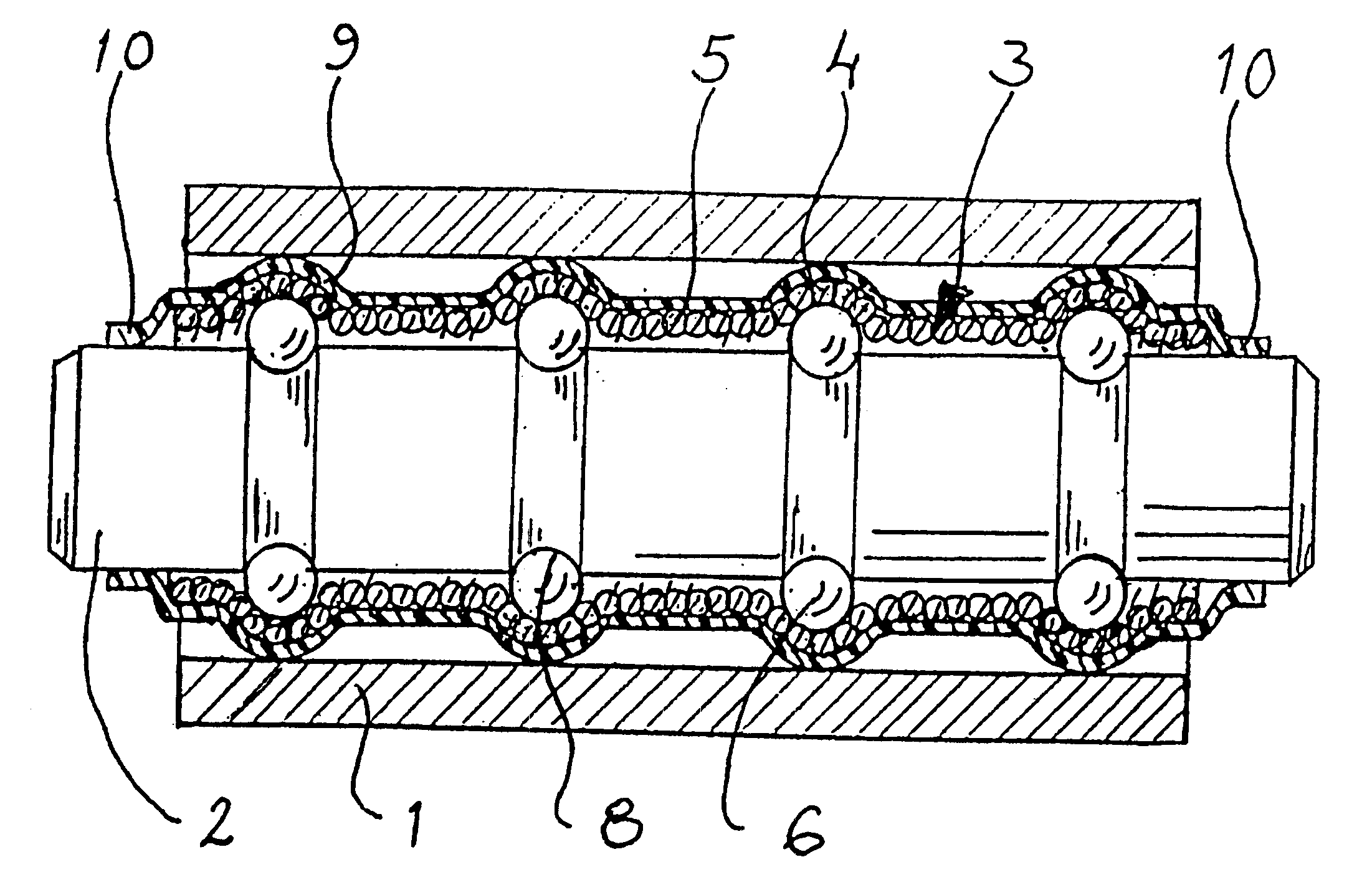
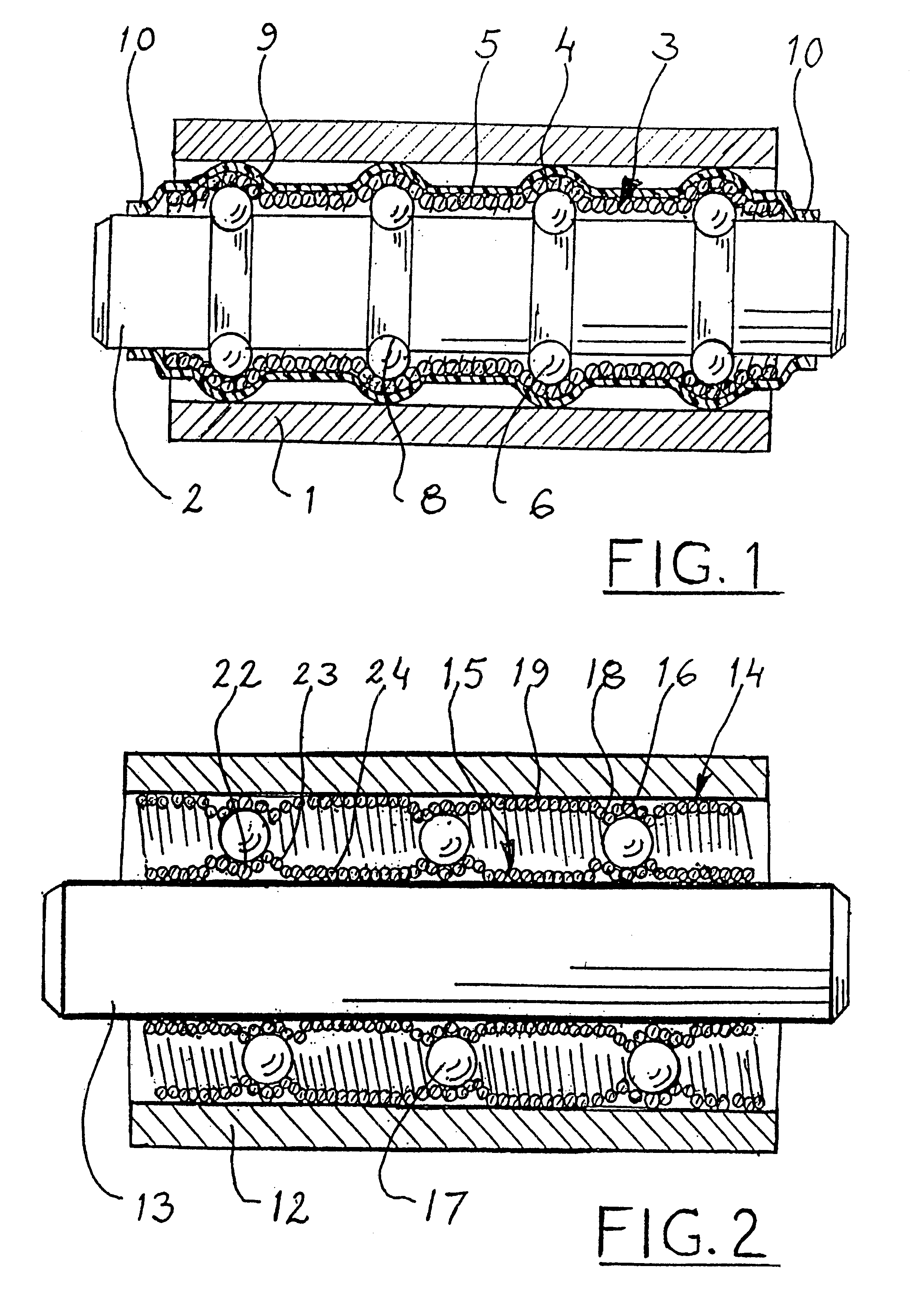
Illustrated in the drawings and described in the following are parts of the machine structure, the components of which are to be journalled to each other for rotary motion by means of the rolling bearing in accordance with the invention. In this context, the two components of the machine structure are divided into an "outer component" and "inner component", which can also be termed the "shaft component". One of these components is connected to a larger complex, such as a stand, a vehicle body or the like, whilst the other component can be denoted as the rotatable or pivotable component. The fixed component can be either the outer component or the inner component, the shaft component. A wheel, for instance, can have a co-rotating axle, journalled in a wheel fork, thereby representing the fixed component. Alternatively, the wheel can be provided with the outer component and be journalled on an axle fixedly attached to a greater structural part.

FIG. 1 shows a ball bearing with several ...


PUM


Abstract

A rolling bearing for journalling an outer machine component (12) for rotary movements in relation to an inner machine component (13). For connection to at least one of the machine components, the bearing comprises corresponding outer and inner main elements, respectively, in the shape of a helical spring (14/15), which is wound to form parts (16/22) supporting rolling surfaces for the rolling bodies (17) of the bearing, which rolling bodies are arranged in an annular raceway. The spring is wound from said supporting part so that it forms a connection part (19/24) in at least one axial direction. These connection parts are arranged to connect and join with further operative parts of the bearing. Examples include parts for connecting the supporting part in question for said rolling surface with further such parts to form a bearing with several rows. Further functions can be to form one or several parts for the assembly and attachment of the helical spring to the respective machine component (12, 13), such as a seat in the outer machine component or an outer envelope for a shaft belonging to the inner machine component.

Description

The present invention relates to a rolling bearing arranged to be connected to other machine components to journal the same during rotation and comprising a number of rolling bodies arranged to roll in an annular raceway around a centre of rotation for the bearing, an outer main element in the form of a ring or tube outside said annular raceway with a rolling surface for the rolling bodies that faces substantially inwards towards the centre of rotation in said annular raceway, and an inner main element with a rolling surface for the rolling bodies that faces substantially outwards away from the centre of rotation in said annular raceway.Rolling bearings of the type specified above for journalling machine components for rotary motion are categorized with respect to the design of the rolling bodies into ball bearings, roller bearings and needle bearings. The two first-mentioned types, in particular, are found in many different sizes and designs for more or less heavy loads and for dif...

Claims


Application Information

Patent Timeline
Patent Type & Authority Patents(United States)
IPC IPC(8): F16C33/58F16C19/02F16C19/18F16C33/61
CPCF16C19/183F16C33/61F16C1/28F16C19/08F16C1/06Y10T74/20444
Inventor DERMAN, KARL GUSTAF
Owner AGORA SA
Why Eureka
Try Eureka