Automatic rise time adjustment for bi-level pressure support system

Inactive Publication Date: 2003-03-18
RIC INVESTMENTS LLC
View PDF10 Cites 311 Cited by
  • Summary
  • Abstract
  • Description
  • Claims
  • Application Information

AI Technical Summary

Problems solved by technology

While the manual rise time selection technique taught by the '274 patent is a step toward increasing patient comfort, it is also burd

Method used


Image

  • Automatic rise time adjustment for bi-level pressure support system
  • Automatic rise time adjustment for bi-level pressure support system
  • Automatic rise time adjustment for bi-level pressure support system

Examples


Embodiment Construction

As discussed above, a bi-level pressure support system provides an inspiratory positive airway pressure (IPAP) during inhalation and an expiratory positive airway pressure (EPAP) during exhalation to the airway of a patient. For most patients requiring bi-level therapy, a higher IPAP pressure is required to maintain airway patency during inhalation, and a much lower EPAP pressure is sufficient to maintain airway patency during exhalation. In fact, it is known to set the EPAP level as low as atmospheric pressure for some patients. By providing bi-level pressure support with the lowest necessary EPAP pressure, the work required for the patient to exhale is reduced and, therefore, the patient's comfort is increased. This, in turn, promotes patient compliance with the prescribed therapy.

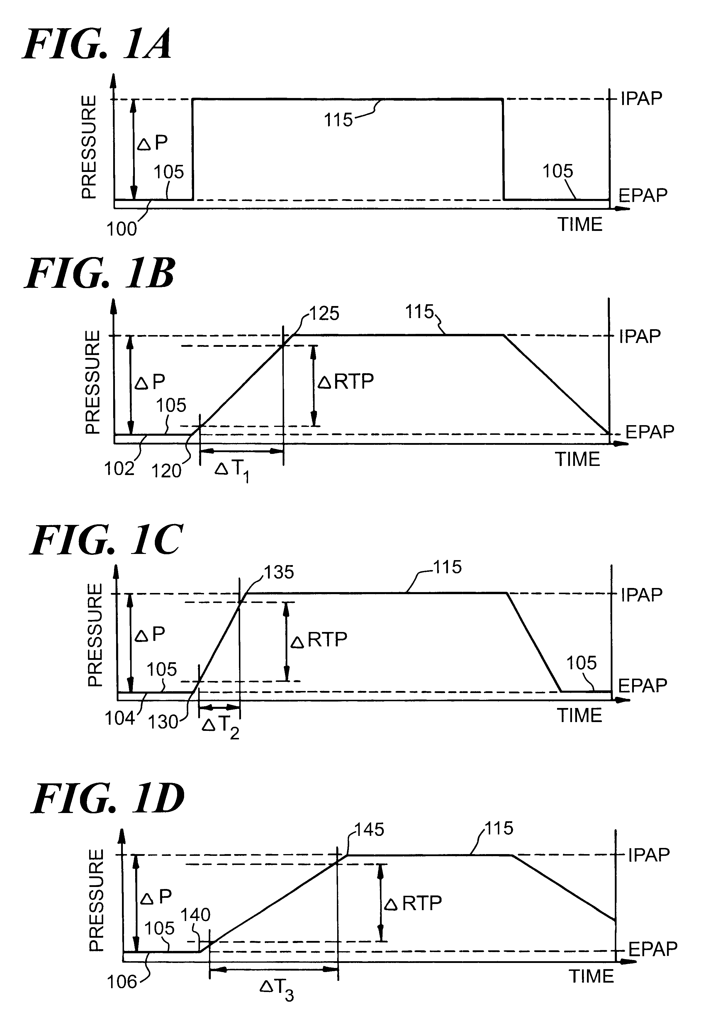
FIG. 1A schematically depicts a theoretical pressure curve 100 output by a bi-level positive airway pressure support system over a portion of a patient's breathing cycle. During an expiratory phase of th...


PUM


Abstract

An apparatus and method for a bi-level positive airway pressure support in which the rise time from the expiratory positive airway pressure to the inspiratory positive airway pressure is automatically controlled by the pressure support system. The pressure support system includes a sensor, a control system, and a pressure generating system. The sensor monitors the patient's respiration to detect respiratory events, such as an apnea, hyponea or other disturbance, and the control system responds to the sensor information to adjust the rise time from the expiratory positive airway pressure to the inspiratory positive airway pressure gas pressure to maximize patient comfort and pressure support treatment effectiveness.

Description

1. Field of the InventionThe present invention generally relates to a bi-level positive airway pressure support system, and, more particularly, to a bi-level pressure support system and method of providing bi-level pressure support in which the rise time from the expiratory phase of pressure support to the inspiratory phase is automatically adjusted.2. Description of the Related ArtPressure support systems that provide a flow of breathing to an airway of a patient at an elevated pressure to treat a medical disorder are well known. One basic form of pressure support system is a continuous positive airway pressure (CPAP) system, which typically involves providing a flow of breathing gas, such as air, to a patient's airway at a constant pressure throughout a patient's breathing cycle. When used to treat obstructive sleep apnea (OSA), for example, this constant pressure is provided at a level sufficient to overcome a patient's airway resistances.It is also known to provide a bi-level po...

Claims


Application Information

Patent Timeline
IPC IPC(8): A61M16/00A61M16/06
CPCA61M16/00A61M16/0066A61M16/06A61M2230/63A61M2016/0039A61M2230/60A61M2016/0021A61M16/0069A61M16/024
Inventor YURKO, GREGORY
Owner RIC INVESTMENTS LLC
Why Eureka
Try Eureka