But such devices have one major limitation: their keyboard keys are presently so small and close together that it is impossible to enter data into them at typical secretarial speed for any length of time.
Indeed, in February 1998 one research manager for a major computer maker (Celeste Baranaski of Hewlett-Packard) said: "Unless some breakthrough is made in keyboard technology, many of these smaller travel keyboards just won't work."
And in that same month a journalist (David MacNeill of Pen Computing
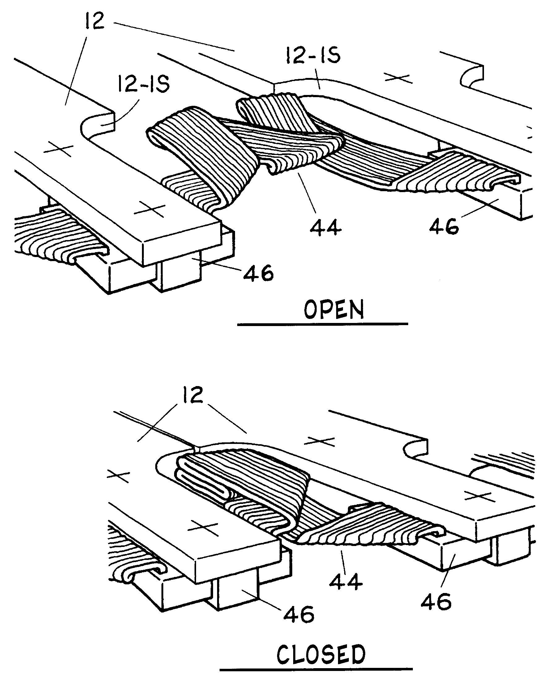
Magazine) Said of present
palmtop computers that their "Inappropriate input methods, such as tiny QWERTY keyboards, hobble us in our attempt to enter our information into a device,
wasting our time, and even causing physical pain."
However, a few inventors have long been aware of this potential deficit of typewriters, computers, laptops, palmtops, calculators, and other
alphanumeric / operational input devices that are designed with versatility and mobility in mind.
But it is obvious that Margolin's invention, while reducing the surface or `
footprint` area occupied by a standard desktop keyboard by about two-thirds, does so at a sacrifice of triply increasing the keyboard's depth, so that such a device could hardly be carried like a videocassette in one's pocket or purse.
A further deficit of Margolin's and Crissan's inventions is that when their keyboards' outer portions are folded onto their central portions, all the keys are concealed so they cannot be used when their keyboards are thusly closed.
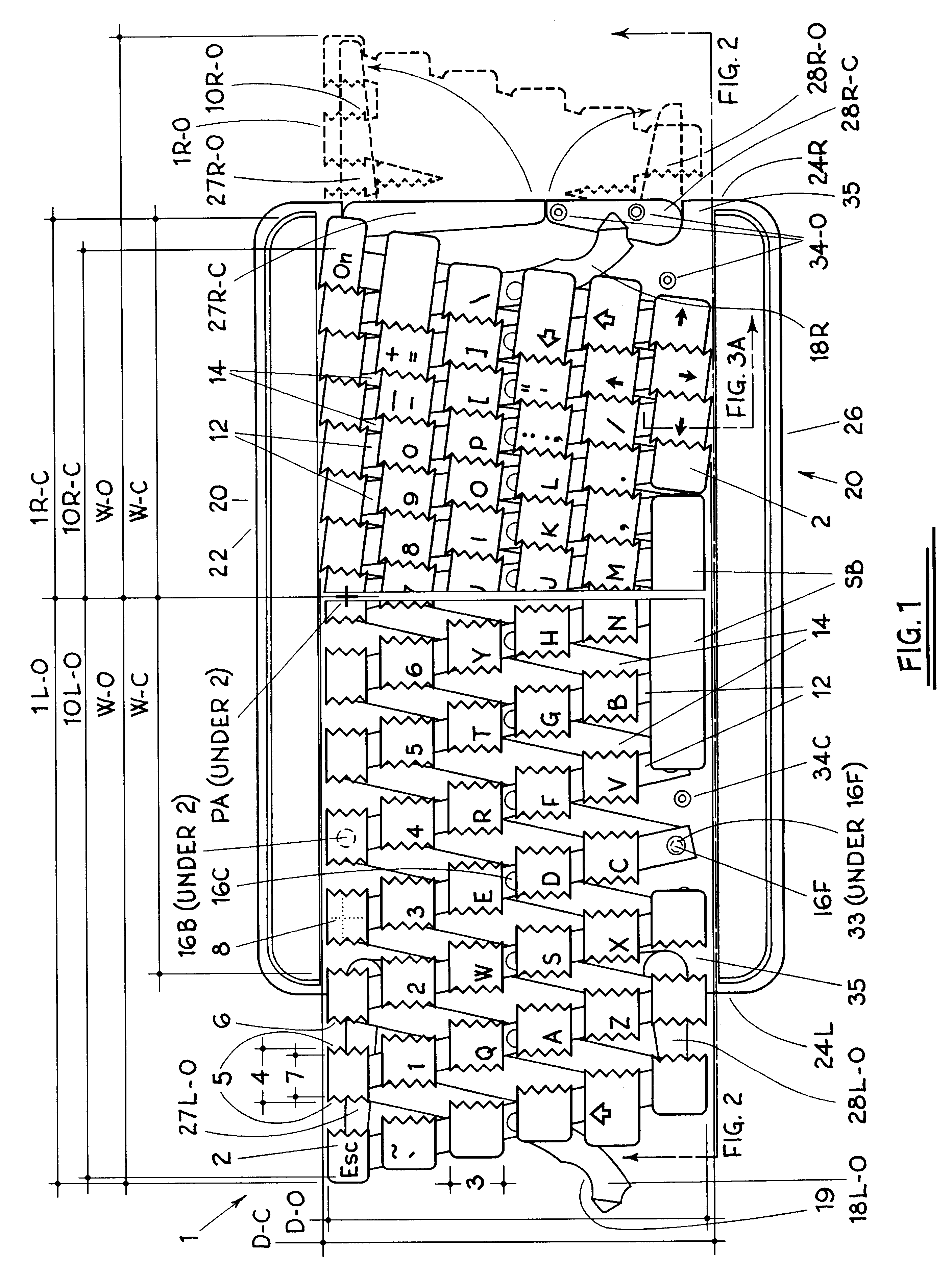
If one looks at a standard keyboard, one will notice a significant amount of space between the sides of any pair of adjacent keys.
Obviously one extreme would be for each key to have its own private circuit to the parent processor; but this of course would be a cumbersome ribbon for a keyboard of more than seventy keys to carry.
Although subsequent improvements in the Disclosed Invention have indicated that the original positional guides / circuitry conductors may not be the optimal solution for these two different functions, recent analysis has indicated another function for such guides which this Disclosure has not yet addressed.
But such guides do not solve a `linkage-
lag` problem revealed by the Invention's prototypes built subsequent to this Patent's original filing: when the closed keyboard is opened, the outer busbars tend to open even wider than their 19 mm spacings before the central bars begin to spread apart, even if the laterally flexible
assembly is precisely made.
1. The tops of each key are dished from front to back, the outer edges of their
interlocking sides are thinner and become gradually thicker toward the key's center, and the continuous edge beneath the key that engages a longitudinal guide projecting from the
busbar below is replaced by two prongs projecting from the key's underside, wherein said prongs engage two similar prongs rising from the
busbar in a manner which holds the key in place when it is poised in unactivated position and allows the key to be removed for purposes of cleaning and repair when an upward leverage is applied under one of its edges.
2. The tiny circular spring beneath each key is replaced by a flexible circular hollow
grommet that collapses to a fraction of its height when pressure is applied to its top.
3. The circuitry that conducts
electronic data from each activated key to the parent
system and is imbedded in the busbars connection to the brace below (see FIG. 3A) is replaced by a paper-thin ribbon of slightly flexible plastic with the key's circuitry printed on its surface and is located separately from the
busbar's connection to the brace below. Many such printed circuitry ribbons can be cheaply made and then
cut, creased, and fitted into or onto the busbars as shown in FIGS. 16 to 23.
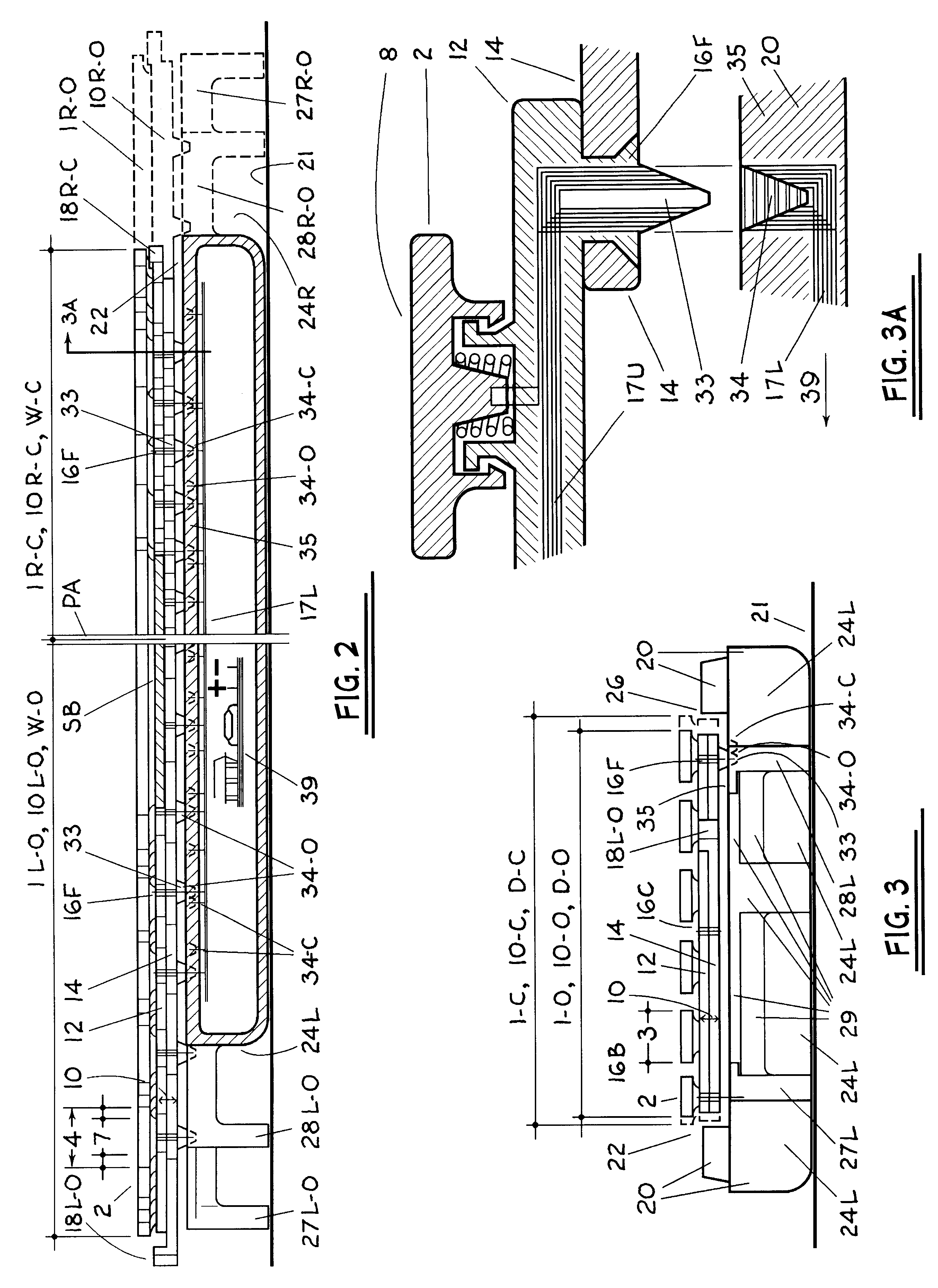
4. Each busbar is no longer a flat bar with a simple rectangular cross-section, but instead is quite thicker as described in two improved embodiments elsewhere in this Specification. However, although the busbar in each embodiment is thicker, the depth of each total key-to-busbar
assembly is less. This is because in the original key-to-busbar
assembly the length of the key's stem was stacked on top of the busbar's depth (see FIG. 3A), but in the improved assemblies the key's stem and the busbar's depth are arranged side to side. Thus no matter how efficiently these components are otherwise made, the new assembly will be less deep than the old; unless the later assembly somehow causes the key's stem or
plunger to lengthen, which here it doesn't. Another aspect of these depth logistics is the relation between a key's
stem length and its travel, that short but important
vertical distance a key moves when it is pressed or activated. Typically a key's
stem length equals its travel plus the length of its guides (the means by which the key is held in a vertical position as it travels). Thus if user ergonomics indicate that a keyboard key should have a travel of at least 2 mm (0.08 in.) to feel comfortable to most users and the length of its guides are added to this, the depth of the key's busbar can be considerably greater than one might think before it will increase the depth of the key-to-busbar assembly and thereby confer this added depth to the parent
system as a whole. Thus it cannot be said of any computer on which this key-to-busbar assembly is mounted that the computer is made narrower at the expense of increasing its depth, no matter how great that depth may be for other reasons.
But on a standard
computer keyboard, each column of keys--say the 3 E D C keys--is not perfectly straight, which has led some commercial examiners of the Disclosed Invention to believe that the Disclosed keyboard when in open position might not duplicate normal
typing as fully as is claimed.
However, some examiners of the Disclosed Invention's original prototypes have expressed concern that such sharp `sawtooth` or `pinking shear` profiles may be tactilely and aesthetically undesirable to a considerable percentage of consumers.
However, there is a logistical reason why the first and sixth rows can possibly be left off the keyboard's laterally flexible assembly.
You can't perform this basic business activity on any other kind of computer today.
If you tried this with a standard-sized
laptop you could dislocate your shoulder.


