Bridge device

a bridge and device technology, applied in the field of bridge devices, can solve problems such as aborting or otherwise severe damage of frames, device not allowing cut-through, and causing problems such as damage to the frame,

Inactive Publication Date: 2003-03-25
MADGE
View PDF19 Cites 22 Cited by
  • Summary
  • Abstract
  • Description
  • Claims
  • Application Information

AI Technical Summary

Problems solved by technology

Problems can arise, however, with the use of a common memory in handling large volumes of data.
There may also be circumstances in which the device does not permit cut-through.
A problem can arise when using a bridge device utilising a common storage means, such as according to the first aspect of the invention, when an aborted or otherwise damaged frame is transmitted through the device.
In the case where this frame is being forwarded across a bridge device using cut-through technology, the transmission of this frame from the output port may have already commenced before it is detected that the frame has been aborted or otherwise severely damaged.
In a typical network protocol, serious disruption can occur if an aborted frame is detected on the network requiring a significant time for the network to re-establish normal operation.
However, in practice, many data frames are considerably smaller than the maximum possible size and this leads to a significant wastage of storage space.
The problem with this approach is that it leads to the need for a large index store.
One of the problems with source routing is the time and complexity required of bridge devices to transmit such broadcast frames to all networks with each frame being differently modified to indicate the identity of the network onto which it is transmitted.

Method used


Image

  • Bridge device
  • Bridge device
  • Bridge device

Examples


Embodiment Construction

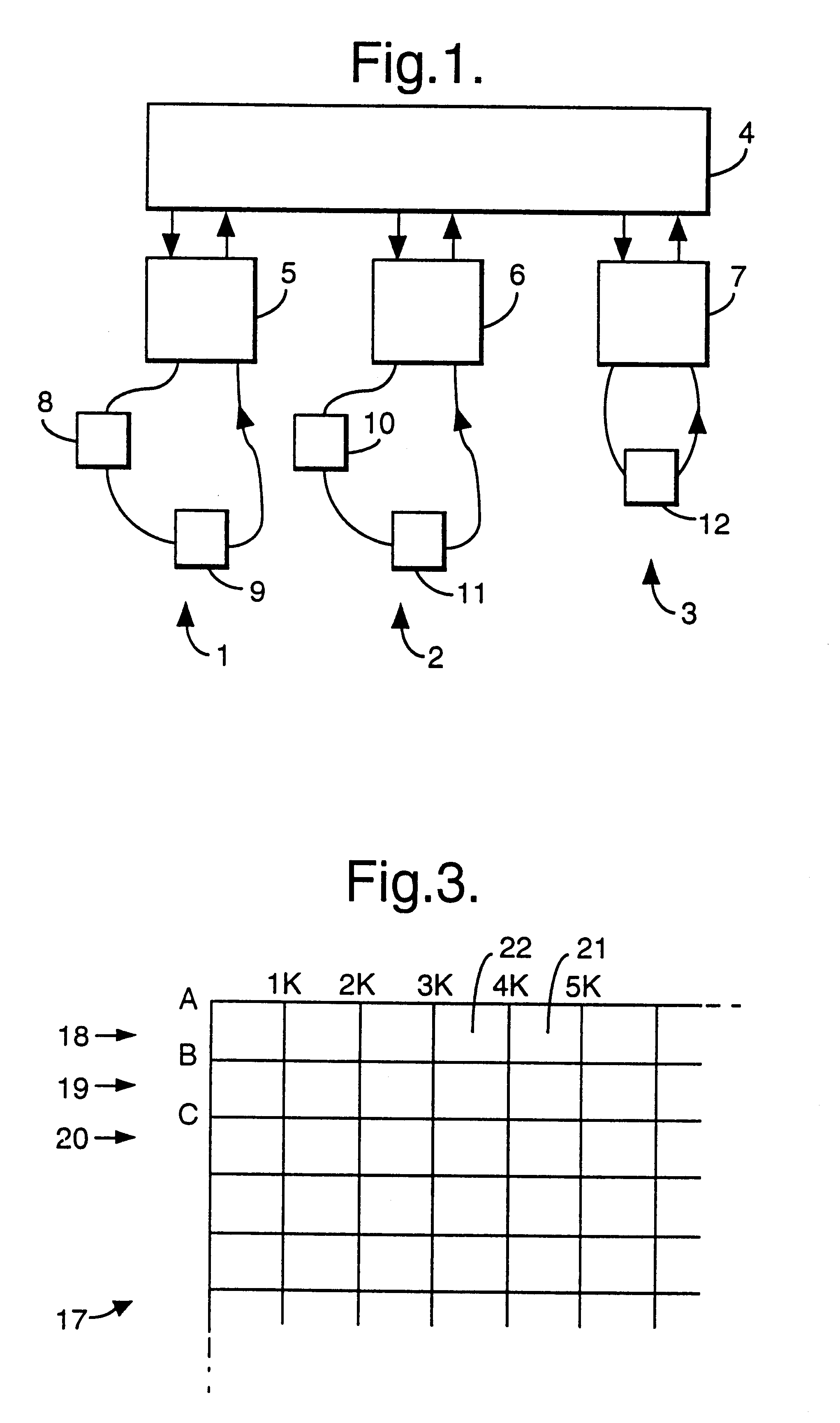
The communications network shown in FIG. 1 comprises three token ring local area networks 1,2,3 each connected to a bridge 4 via respective coupling devices 5,6,7. The local area network 1 has a pair of end stations 8,9, the local area network 2 has a pair of end stations 10,11 and the local area network 3 has a single end station 12. In practice, each local area network is likely to have a much larger number of end stations such as PCs, file servers and the like but for clarity only a small number is shown in the drawing. Each of the local area networks 1,2,3 is self-contained in the sense that data in the form of frames can be transmitted around the network through the coupling devices 5-7 in a conventional manner without passing through the bridge 4. However, occasionally it will be necessary for an end station on one network to communicate with an end station on another network. For example, the end station 8 may wish to communicate with the end station 12. In that case, communi...


PUM


Abstract

A bridge device (4) for connecting a plurality of communication networks (1-3) around which data is transmitted in frames which include control information defining at least the identity of a destination for data in the frame, each network having at least one end station (8-12). The bridge device comprises a corresponding plurality of data coupling units (13,14) for connection to respective ones of the networks (1-3), each data coupling unit including receive (13) and transmit (14) interfaces for respectively receiving data from and transmitting data onto the connected network. A common store (17) is connected to all the data coupling units for receiving data being transmitted from one network to another. A controller (16,28) controls the routing of data through the bridge device (4) via the common store (17), the controller causing incoming data to be routed to a destination network before the data has been fully stored in the common store, if predetermined conditions are satisfied, the controller being adapted to monitor the amount of free space in the common storage means and to prevent the supply of data to the common store if the available free space is less than a predetermined amount.

Description

The invention relates to a bridge device for connecting a plurality of self-contained communication networks around which data is transmitted in frames which include control information defining at least the identity of the destination for data in the frame, each network having at least one end station.DESCRIPTION OF THE PRIOR ARTExamples of networks to which the invention apply include token passing rings as well as FDDI and ATM networks.In typical local area network installations, it has been possible in the past to use a single network to achieve communication between a number of end stations such as PCs, file servers and the like. However, with the need to provide more and more end stations, it has been the practice to divide the overall system up into a number of individual local area networks (for example one per floor) and to connect the networks together via bridge and other devices. Most of the time, an end station on a network will only wish to transmit to another end stat...

Claims


Application Information

Patent Timeline
Patent Type & Authority Patents(United States)
IPC IPC(8): H04L12/56H04L12/46
CPCH04L12/4625H04L49/90H04L49/9078H04L49/9047H04L49/901
Inventor BARBER, SIMON DAVIEDENT-YOUNG, CRISPIN NICHOLASSABEY, CHRISTOPHER GUYCURNYN, JONATHANPEARCE, DAVID ANDREW JAMESWARWICK, TREVOR
Owner MADGE
Why Eureka
Try Eureka