Highway crash barrier monitoring system

a monitoring system and crash barrier technology, applied in the direction of instruments, apparatus for force/torque/work measurement, roads, etc., can solve the problems of high approach cost, high crash barrier damage, and increased risk of collision vehicle,

Inactive Publication Date: 2003-03-25
ENERGY ABSORPTION SYST
View PDF20 Cites 26 Cited by
  • Summary
  • Abstract
  • Description
  • Claims
  • Application Information

AI Technical Summary

Benefits of technology

Additionally, the collision sensor is coupled with a digital camera that is controlled to store one or more images in response to detection of a collision by the collision sensor. These stored images help in identifying the vehicle involved in the collision. This can be important in situations where the colliding vehicle has a responsibility to the highway department to defray expenses associated with damage to the crash barrier.

Problems solved by technology

Once a collision has occurred between a vehicle and a highway crash barrier, the crash barrier is often damaged.
Such a second collision can expose the colliding vehicle to increase risks.
This approach is expensive, because it requires an inspector to travel to the site of the highway crash barrier.
Also, this approach provides the disadvantage that a considerable time period may elapse between the time a crash barrier is damaged in a collision and the time of the next inspection.

Method used


Image

  • Highway crash barrier monitoring system
  • Highway crash barrier monitoring system
  • Highway crash barrier monitoring system

Examples


Embodiment Construction

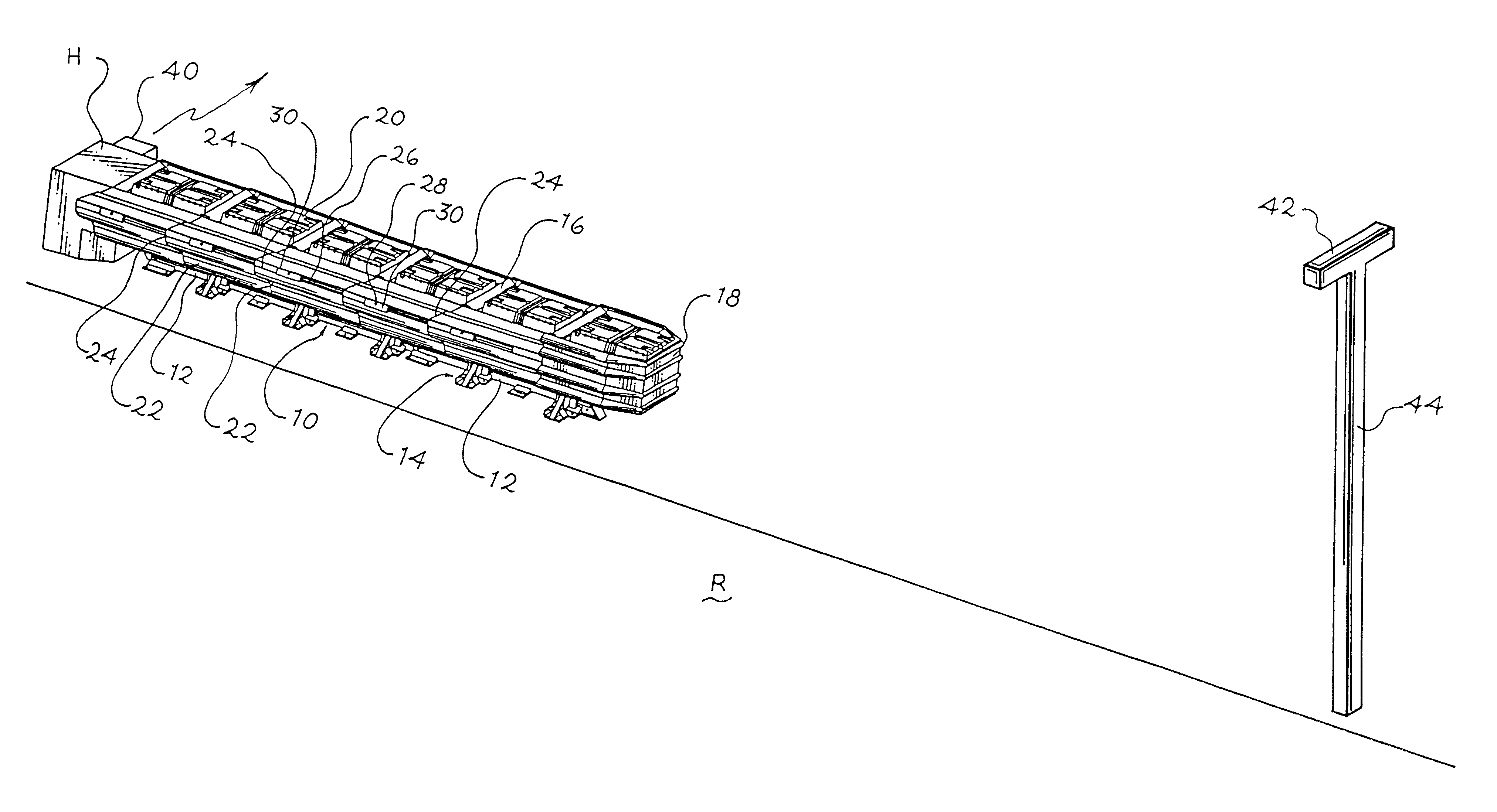
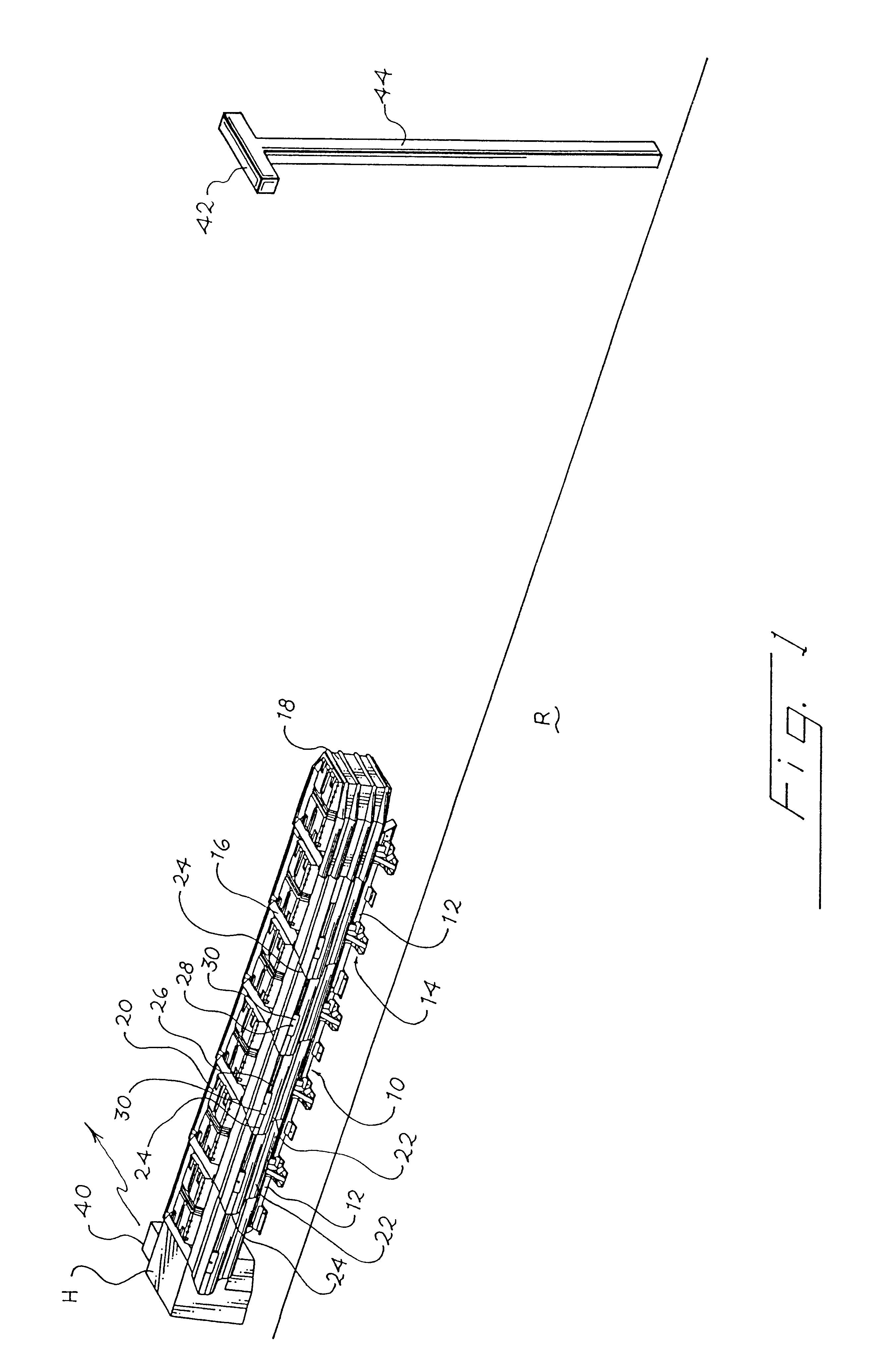
Turning now to the drawings, FIG. 1 shows a perspective view of a crash barrier 10 installed alongside a roadway R in front of a hazard H. The crash barrier 10 in this example includes a rail 12 that supports an array of legs 14 for sliding motion along the rail 12. Each of the legs 14 supports a diaphragm 16, and energy absorbing cartridges 20 are positioned between adjacent diaphragms 16. A nose piece 18 surrounds the forward energy absorbing cartridge 20.

The diaphragms 16 support fender panels 22 extending in overlapping fashion along each side of the crash barrier 10. The forward portion of each fender panel 22 is bolted to a respective one of the diaphragms 16, and the trailing edge 24 of each fender panel 22 overlaps the leading edge of the next rearwardly-adjacent fender panel 22. Each fender panel 22 defines a longitudinal slot 26, and a fastener 28 extends through each slot 26 and is coupled at one end to a respective one of the diaphragms 16 and at the other end to a washe...


PUM

PropertyMeasurementUnit
speedsaaaaaaaaaa
energy absorbingaaaaaaaaaa
energyaaaaaaaaaa

Abstract

A highway crash barrier includes a collision sensor that detects when a vehicle collides with the crash barrier. A transmitter is coupled with the collision sensor to transmit a radio frequency signal to a remote location when this collision sensor detects a collision. This radio frequency signal includes a fault message that is forwarded automatically to a user responsible for maintenance of the crash barrier. A camera is controlled in response to the collision sensor to store an image of the crash barrier shortly after the collision.

Description

REFERENCE TO MICROFICHE APPENDIXThis specification includes a microfiche appendix including 2 sheets of microfiche and a total of 190 frames. This microfiche appendix includes copyrighted subject matter. The owner of the copyright reserves all copyright rights whatsoever, other than the right to reproduce the microfiche appendix in facsimile form as a part of this specification.The present invention relates to highway crash barriers, and in particular to systems for remotely reporting a collision of a vehicle with a crash barrier.Highway crash barriers are commonly positioned alongside a roadway to protect occupants in a vehicle that has left the roadway. Such crash barriers often include an energy absorbing system that protects the vehicle occupants against high decelerations in a collision.Once a collision has occurred between a vehicle and a highway crash barrier, the crash barrier is often damaged. It is important that damaged crash barriers be repaired or replaced promptly to m...

Claims


Application Information

Patent Timeline
Patent Type & Authority Patents(United States)
IPC IPC(8): E01F15/00E01F15/14E01F1/00G01L5/00G08C17/00G08G1/00G08G1/04
CPCE01F15/146
Inventor GEARY, JEFFREY A.SMITH, DAVID A.
Owner ENERGY ABSORPTION SYST
Why Eureka
Try Eureka