
Channel allocation in cellular telephony

a channel allocation and cellular telephony technology, applied in network planning, electrical equipment, network traffic/resource management, etc., can solve the problems of liable to interference, limited number of radio channels which the operator is permitted to use, and possible interference between phone calls

Inactive Publication Date: 2003-03-25
BRITISH TELECOMM PLC
View PDF14 Cites 34 Cited by
  • Summary
  • Abstract
  • Description
  • Claims
  • Application Information

AI Technical Summary

Problems solved by technology

The number of radio channels which the operator is permitted to use is limited, and there are not enough for each phone call in the network to be carried on a different channel.
This introduces the possibility of interference between phone calls.
`Adjacent channel` interference, due to another call using a different channel, is also a problem: a call made on a channel corresponding to a frequency band of 4000-4025 kHz is liable to interference from a call on the adjacent band; 4025-4050 kHz.
Adjacent channel interference can occur between two calls in the same cell, as well as between adjacent cells.
The problem facing the network operator is to allocate channels to base stations such that demand for channels across the network is met, while keeping interference within acceptable levels.
These aims are clearly in conflict: the more channels allocated to each base station the harder it is to plan the channel reuse to avoid unacceptable interference.
An added difficulty is that the demand across the network is neither uniform nor static.
Even worse, for efficient channel allocation, are the unpredictable fluctuations in demand resulting from events such as road accidents.
However, online planning requires operation in real time, and is thus more demanding of processing power.
Producing an efficient channel allocation plan is not only an important part of running an efficient mobile network, it is a formidable abstract mathematical problem.
Clearly an exhaustive search of solution space is not an appropriate method for optimising such a problem.

Method used


Image

  • Channel allocation in cellular telephony
  • Channel allocation in cellular telephony
  • Channel allocation in cellular telephony

Examples


Embodiment Construction

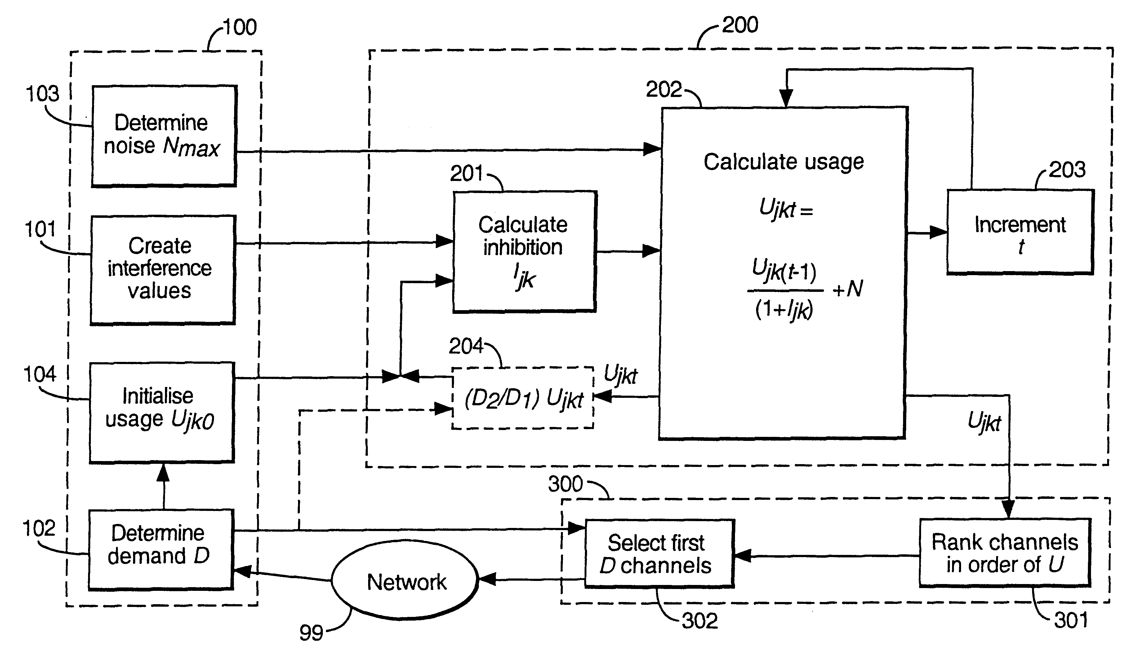
FIG. 1 is a schematic diagram illustrating the various functional elements of the process. These may be embodied as software on a general purpose computer. The process of producing a channel allocation plan begins with an initialisation phase of assembling the necessary information (phase 100). This is followed by an iterative progression from homogeneity towards a solution (phase 200). A solution can be extracted (phase 300) at any time but the quality of that solution improves as time goes on.

In the initialisation phase (100) an interference table is first provided (step 101). This is a j.times.j table (where j is the number of cells) which gives a value to the strength with which each cell can cause interference in each other cell. Separate tables may be used for co-channel interference and adjacent channel interference, but in both cases the full j.times.j table is used. Thus if better data is available concerning the interference values between two cells it can be incorporated ...


PUM


Abstract

A channel allocation process for a cellular telephone network starts from a position of homogeneity in which each base station has the potential to use all channels. It develops ever greater heterogeneities by processing a combination of short and medium range interactions between the base stations themselves, causing each base station of the cellular telephone network to inhibit its neighbors from using a given channel, to generate a usage factor for each channel in each cell indicative of the level of interference to be expected on that channel in that cell. Channels can then be allocated to each base station according to the ranking of the usage factors determined for the channels at that base station. The entire network may be emulated by a single processor, controlling the base stations of the network in accordance with the results of the process. Alternatively, each base station of the network performs that part of the process relating to itself, in co-operation with its neighbors, and utilizes channels in accordance with results.

Description

1. Field of the InventionThis invention relates to channel allocation in cellular telephony, and in particular to a method for dynamically allocating channels to cells according to demand.2. Related ArtA cellular telephone network consists of a number of fixed base station transceivers and a much larger number of mobile handsets which communicate with base stations via a radio channel. The number of radio channels which the operator is permitted to use is limited, and there are not enough for each phone call in the network to be carried on a different channel. Thus a central principle of such networks is channel reuse (Lee, W. C. Y.: Mobile Cellular Telecommunications Systems. McGraw-Hill Book Company, New York, 1989): at any time many base stations may be transceiving on each channel. This introduces the possibility of interference between phone calls. Interference from other calls using the same channel is known as `co-channel interference`. `Adjacent channel` interference, due to...

Claims


Application Information

Patent Timeline
IPC IPC(8): H04Q7/36H04W16/10
CPCH04W16/10H04W92/20H04W28/16H04W28/04
Inventor TATESON, RICHARD E
Owner BRITISH TELECOMM PLC
Learn More