

Process for determining the position of a moving object using magnetic gradientmetric measurements
a technology of magnetic gradient and position determination, applied in the direction of speed measurement using gyroscopic effects, gyroscope/turn-sensitive device, reradiation, etc., can solve the problems of not being able to guarantee, not being able to compensate for the displacement of the object, and not being able to adapt well to the measurement of magnetic fields at low frequencies
- Summary
- Abstract
- Description
- Claims
- Application Information
AI Technical Summary
Problems solved by technology
Method used
Image

Examples
Embodiment Construction
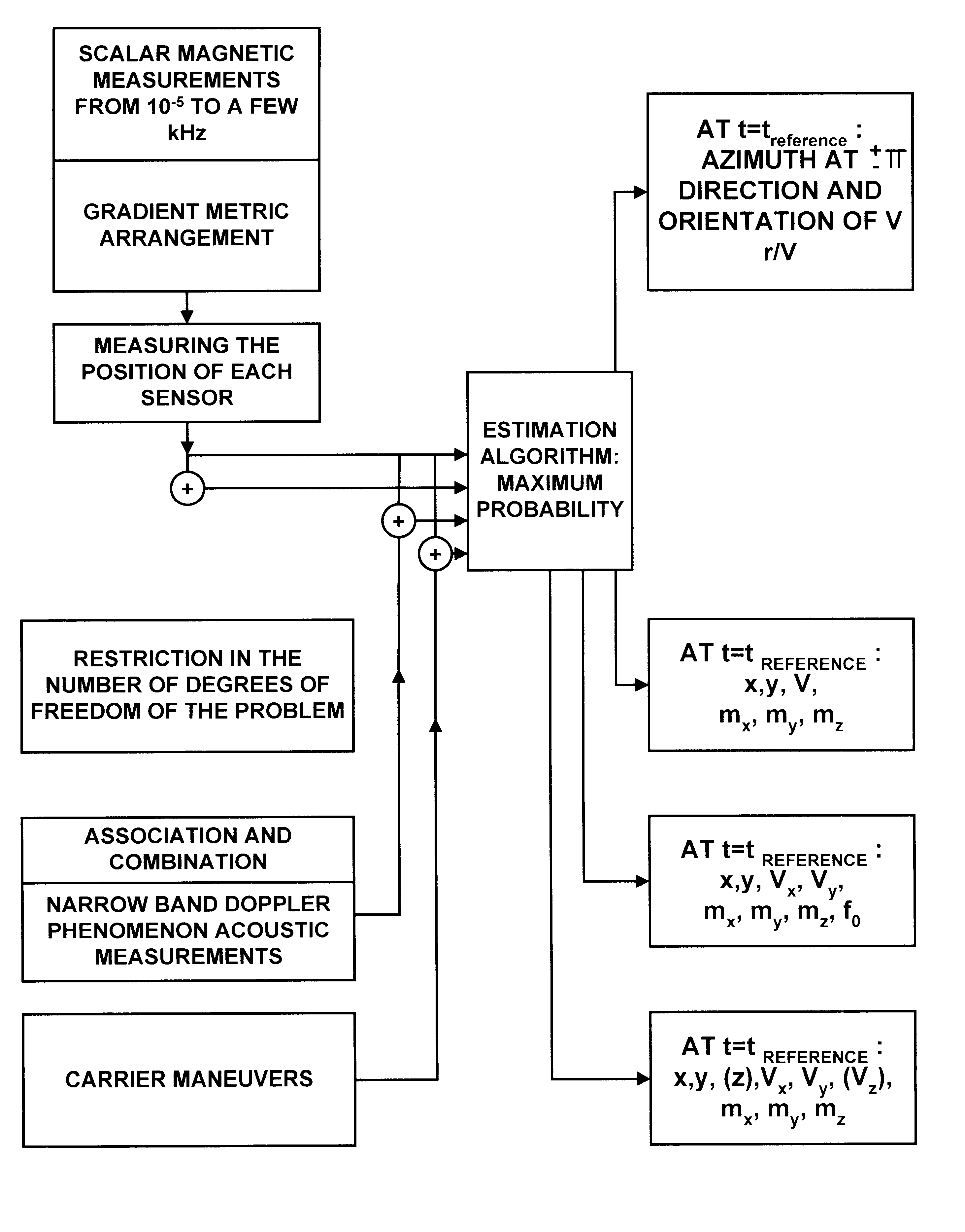
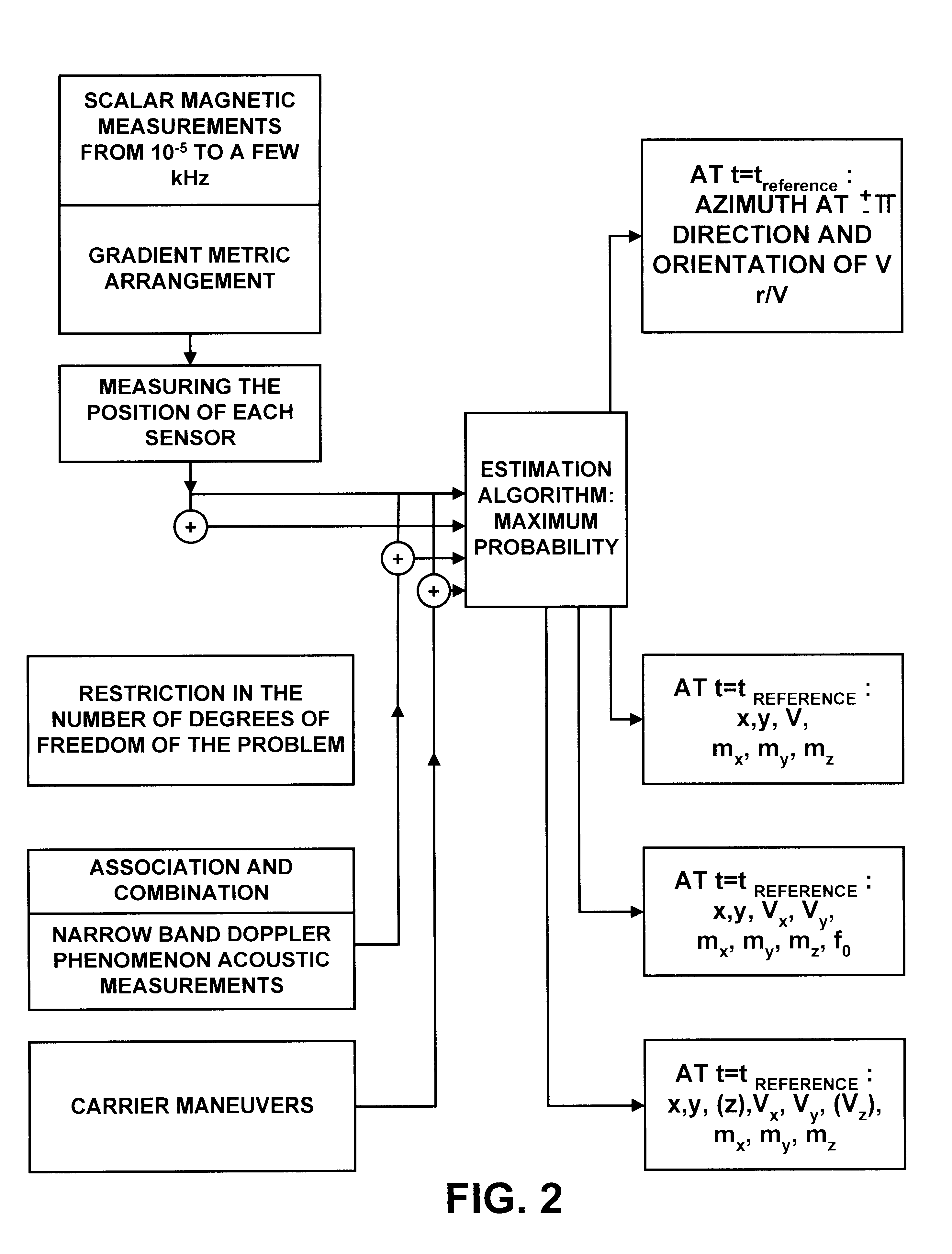
The invention relates to a process for determining the position of a moving object characterized in that it comprises the following steps:
scalar measurements are acquired by a set of electromagnetic sensors all installed on the same site, at a position known at each instant;
the trajectory of the object is determined approximately by a model;
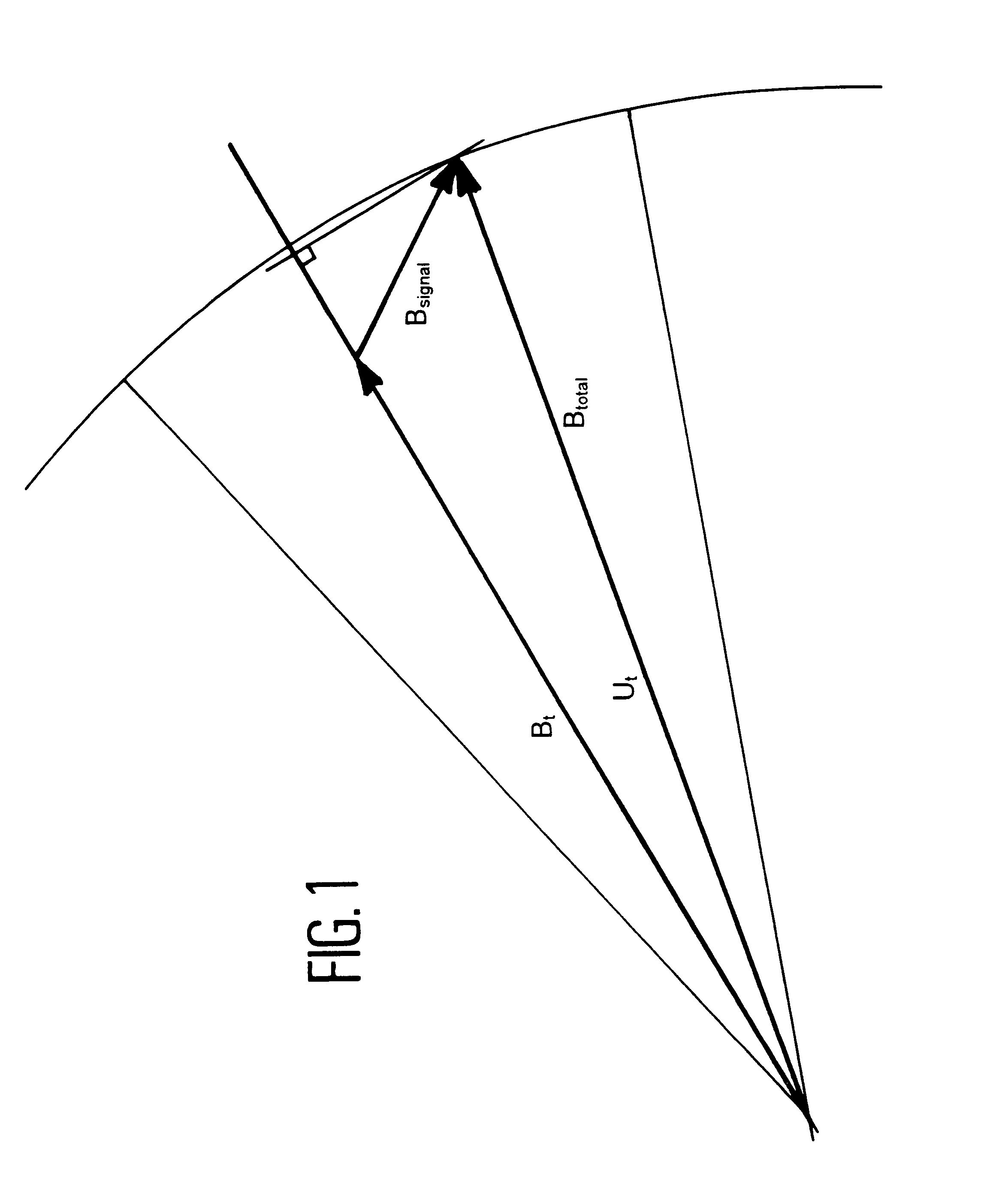
the measurements output from each sensor are combined to obtain spatial gradient measurements representative of the vector electromagnetic disturbance of the moving object;
a vector of parameters characteristic of the model is estimated as a function of gradient measurements and as a function of the position of the sensors;
the position of the object is determined as a function of the position of the sensors and the parameters vector.
Advantageously, the following variants are possible:
in a first variant, on which others depend, electromagnetic measurements output from scalar magnetometers used in gradientmeters are used;
in a second variant, the mov...
PUM
 Abstract
Description
Claims
Application Information