Multiturn rotary encoder with multiple code carriers coupled by a reduction gear

Inactive Publication Date: 2003-04-01
DR JOHANNES HEIDENHAIN GMBH
View PDF26 Cites 77 Cited by
  • Summary
  • Abstract
  • Description
  • Claims
  • Application Information

AI Technical Summary

Problems solved by technology

It is disadvantageous in connection with this multi-turn rotary encoder that a code disk with several code tracks must be used in order to generate a multi-digit code word.
It is disadvantageous here that it is necessary to mount the Hall sensors individually on a plate.

Method used


Image

  • Multiturn rotary encoder with multiple code carriers coupled by a reduction gear
  • Multiturn rotary encoder with multiple code carriers coupled by a reduction gear
  • Multiturn rotary encoder with multiple code carriers coupled by a reduction gear

Examples


Embodiment Construction

)

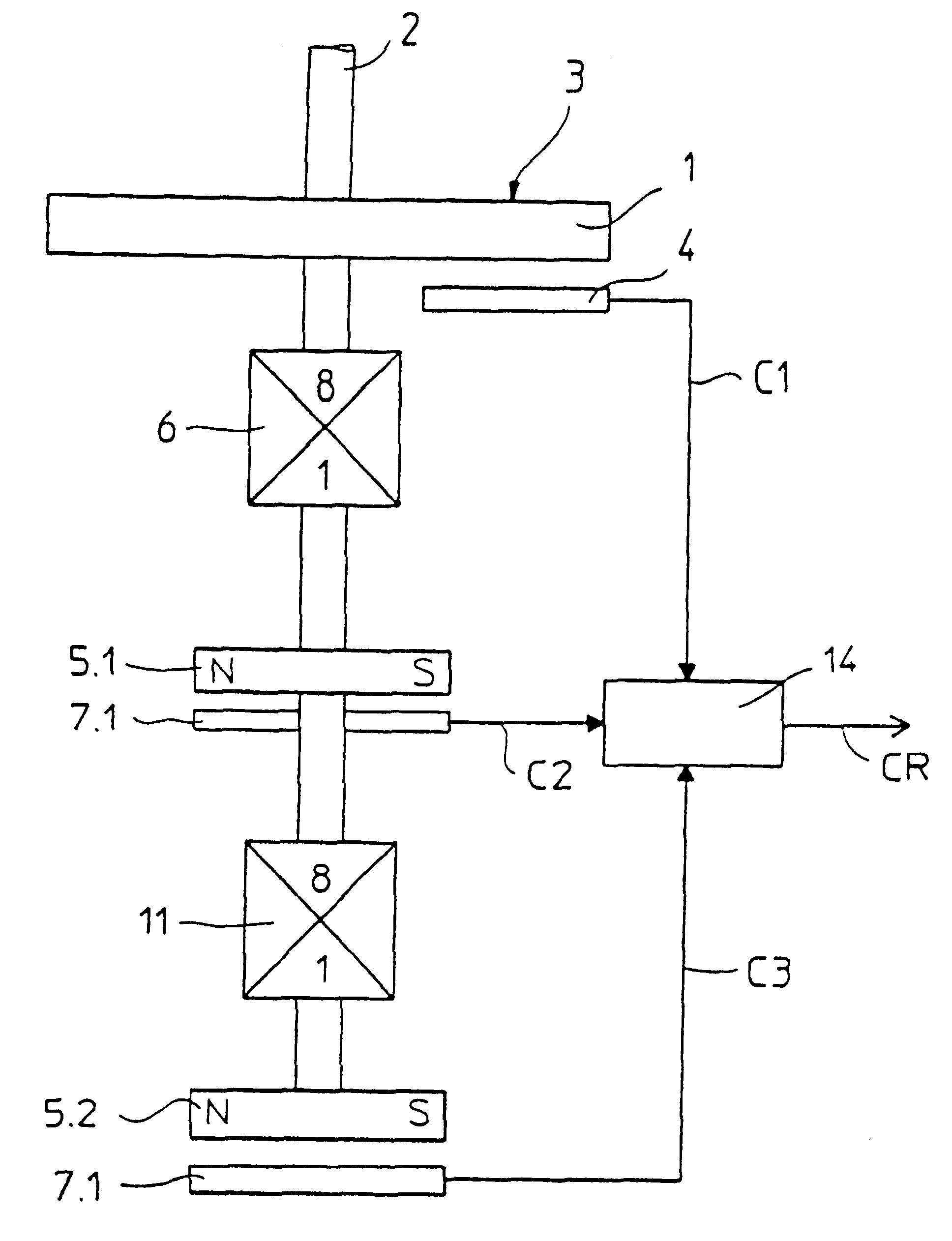
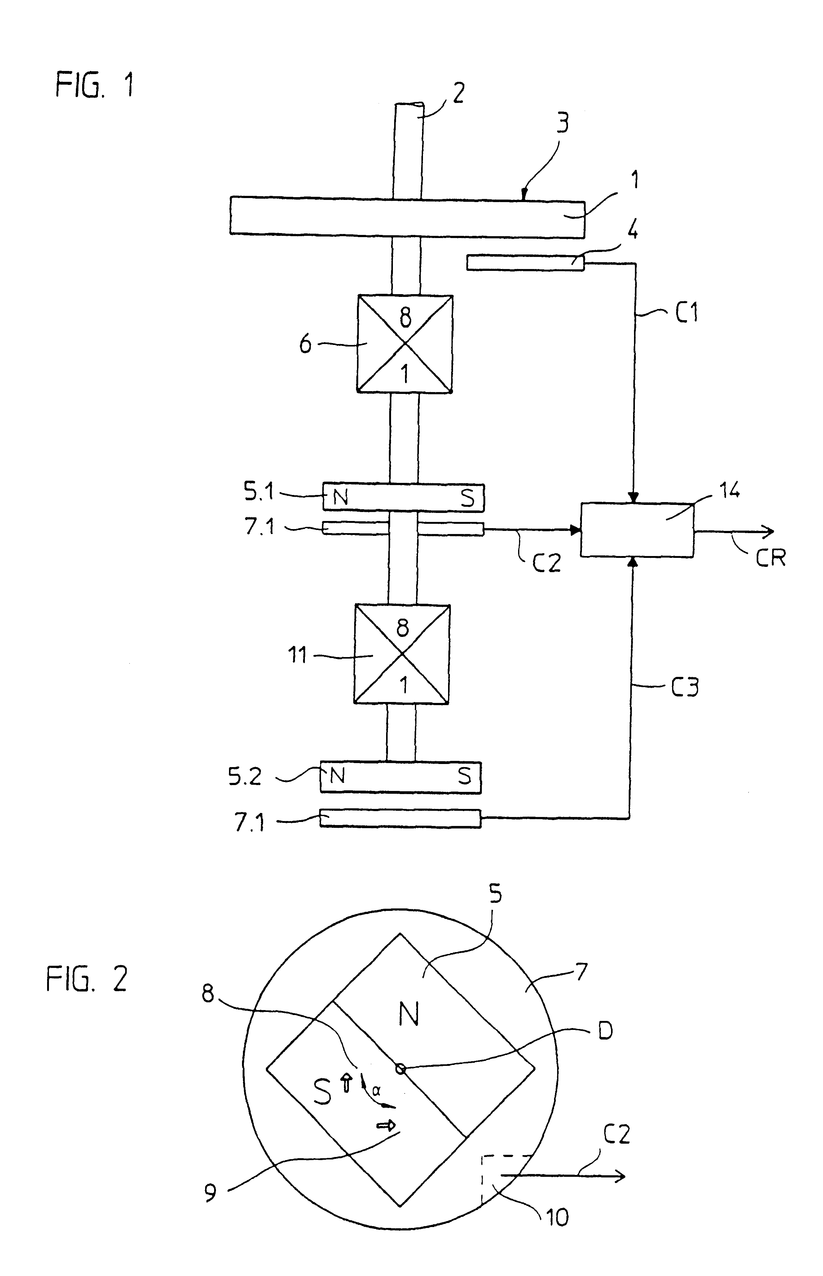
The principle of a multi-turn rotary encoder is represented in FIG. 1. It includes a single-turn element and a multi-turn element. The single-turn element includes a code disk 1, which is directly coupled with the input shaft 2 which is to be measured. The code disk 1 has a coding 3, which can be scanned in an opto-electrical, magnetic, capacitive or inductive manner in order to divide a revolution of the input shaft 2 into a plurality of differentiable sectors. Usually this coding 3 is a multi-track Gray code, however, it can also be formed by a single-track chain code. The coding 3 is scanned by a scanning device 4, so that a multi-digit code word C1 is present at the output of the single-turn element, which indicates the absolute position of the input shaft 2 within a single revolution.

The multi-turn element is provided for detecting the number of revolutions of the input shaft 2. It includes at least one code carrier 5.1, which is coupled with the input shaft 2 by a reduction g...


PUM


Abstract

A multi-turn rotary encoder that includes a first code carrier connected with an input shaft, a scanning device that scans the first code carrier and generates an absolute position of the input shaft within one revolution, and a digital code word is present at an output of the scanning device and a second code carrier for measuring the number of revolutions of the input shaft. A reduction gear is arranged between and coupled to the first and second code carriers. The second code carrier includes a magnetic body with at least one north and south pole and a substrate with a spatial arrangement of sensor elements integrated therein, which are sensitive to magnetic fields, is associated with the magnetic body. An evaluation circuit integrated into the substrate, wherein scanning signals, which are phase-shifted with respect to each other, from the sensor elements are supplied, and that the evaluation circuit combines the scanning signals in such a way that a second digital code word is present serially or in parallel at an output of the evaluation circuit. A combination logical device, which is supplied with the first and second digital code words and which forms a resultant multi-digit code word therefrom.

Description

Applicants claim, under 35 U.S.C. .sctn. 119, the benefit of priority of the filing date of May 6, 1998 of a German patent application, copy attached, Serial Number 198 20 014.5, filed on the aforementioned date, the entire contents of which is incorporated herein by reference.1. Field of the InventionIt is necessary in many cases to absolutely determine the position of a shaft within one revolution, as well as the number of revolutions. Multi-turn rotary encoders are employed for this purpose, such as those described in EP 0 715 151 B1 and DE 42 20 502 C1. EP 0 715 151 B1 corresponds to U.S. Pat. No. 5,734,266, the entire contents of which are incorporated herein by reference.2. Description of the Related ArtThe multi-turn rotary encoder in accordance with EP 0 715 151 B 1 is described on page 9 of the HEIDENHAIN Company Prospectus: Code-Drehgeber [Rotary Encoder], April 1997. Several code disks are connected with each other by a gear for the detection and differentiation of a plur...

Claims


Application Information

Patent Timeline
Patent Type & Authority Patents(United States)
IPC IPC(8): G01B7/30G01D5/14G01D5/245G01D5/12G01B7/00
CPCG01B7/30G01D5/2458G01D5/145G01D2205/26
Inventor BIELSKI, STEFFENFEICHTINGER, KURTSPIES, ALFONSSTRASSER, ERICHMITTERREITER, JOHANNMEYER, HERMANNSCHROTER, ANDREAS
Owner DR JOHANNES HEIDENHAIN GMBH
Why Eureka
Try Eureka