Enhanced module kick-out spring mechanism for removable small form factor optical transceivers

a technology of optical transceivers and enhanced modules, applied in the direction of coupling device connections, coupling parts engagement/disengagement, incorrect coupling prevention, etc., can solve the problems of reducing the effectiveness of reducing the effectiveness of reducing the effectiveness of reducing the effect of reducing the effectiveness

Inactive Publication Date: 2003-04-08
LUMENTUM OPERATIONS LLC
View PDF6 Cites 22 Cited by
  • Summary
  • Abstract
  • Description
  • Claims
  • Application Information

AI Technical Summary

Benefits of technology

If the spring force constants of the opposing kick-out and secondary springs are substantially equal, both opposing springs will deform or deflect a substantially similar amount. If one of the opposing springs has a spring force constant greater than the other, the spring with the smaller spring force constant will deflect a greater amount than the spring with the larger spring force constant. The spring with the larger spring force constant may cause the other opposing spring to deform or deflect beyond its yield point and acquire a permanent set or deformation, thereby reducing its effectiveness and its ability to exert its design force on the opposing spring or, subsequently, it may cause the overly deflected spring to break.
To overcome this possible physical failure and prevent a reduction in effectiveness, the spring with the smaller spring force constant may be blocked at its maximum design limit of travel by an over-travel stop. The weaker spring will abut the over-travel stop when fully deflected by the stronger spring and the stronger spring then may continue to deflect as it is further loaded. This will permit the opposing springs to exert disconnection and ejection forces over a larger span of linear travel of the transceiver module and will insure that adequate ejection forces remain available from the kick-out springs to be exerted on the transceiver module once the transceiver module connector has been unlatched and disconnected from the mating connector.

Problems solved by technology

The transceiver modules typically are densely populated on an exterior panel of a computer housing or server housing and, accordingly, are difficult to grasp and extract from their respective ports, primarily due to size and spacing between adjacent ports.
The difficulty of grasping the transceiver modules is exacerbated both by a very small surface of a fully inserted and latched transceiver module which protrudes from the computer or server housing, and the close proximity of similar adjacent modules does not allow adequate finger space to reach in order to grasp the modules.
While the transceiver module protrudes a small distance from the computer or server housing in its fully latched and installed position, the small amount of the transceiver module protruding from the housing is difficult, if not insufficient, to be easily grasped by fingers in order to extract the transceiver module from the housing.
Whenever the frictional forces of engagement and connection of the connector on the transceiver module with the connector resident within the host computer or server housing are excessive relative to the kick-out spring force, the transceiver module may not adequately respond to the unlatching of the transceiver module; and once the unlatching force is released, the latch may not have displaced sufficiently to prevent the latch from re-engaging the mating latch surface.
This may overstress the cable or cable fitting and damage it to the point of being unusable.
This procedure poses a substantial risk of damaging the transceiver module, a relatively expensive item.
The causes for improper and insufficient ejection of the transceiver modules may be due not only to excessive frictional forces between the connectors, but also due to insufficient deformation of the kick-out spring during insertion.
Such insufficient deformation can result from a permanent set in the kick-out spring resulting in inadequate restoration movement and lack of adequate kick-out spring force over the entire range of movement required to fully disengage the mating connectors and to eject at least partially the transceiver module.
Due to size limitations, the kick-out spring is relatively weak and has a limited range of deformation before becoming over-stressed.
The range of motion through which a kick-out spring may be displaced or deformed is inherently limited by the design and choice of materials for the spring.
The spring with the larger spring force constant may cause the other opposing spring to deform or deflect beyond its yield point and acquire a permanent set or deformation, thereby reducing its effectiveness and its ability to exert its design force on the opposing spring or, subsequently, it may cause the overly deflected spring to break.

Method used


Image

  • Enhanced module kick-out spring mechanism for removable small form factor optical transceivers
  • Enhanced module kick-out spring mechanism for removable small form factor optical transceivers
  • Enhanced module kick-out spring mechanism for removable small form factor optical transceivers

Examples


Embodiment Construction

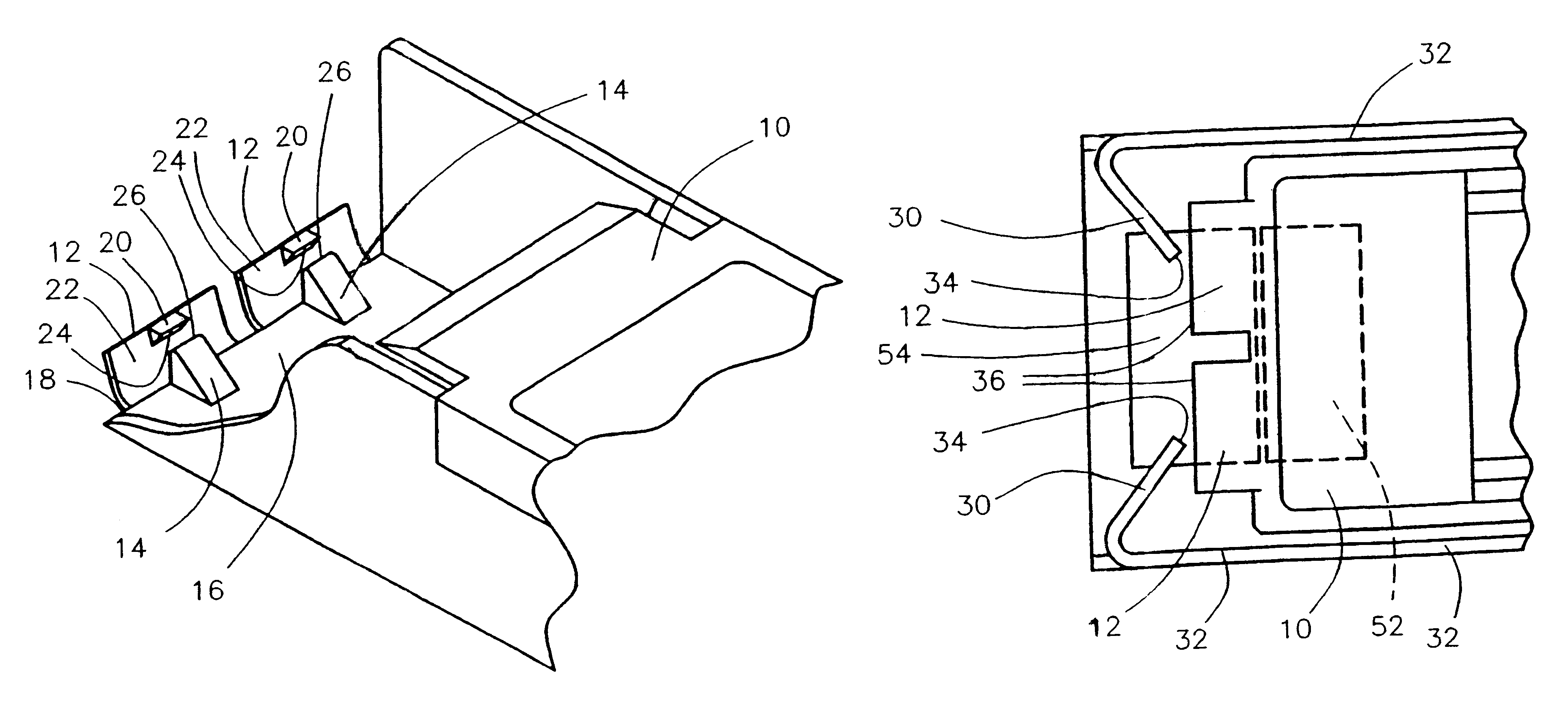
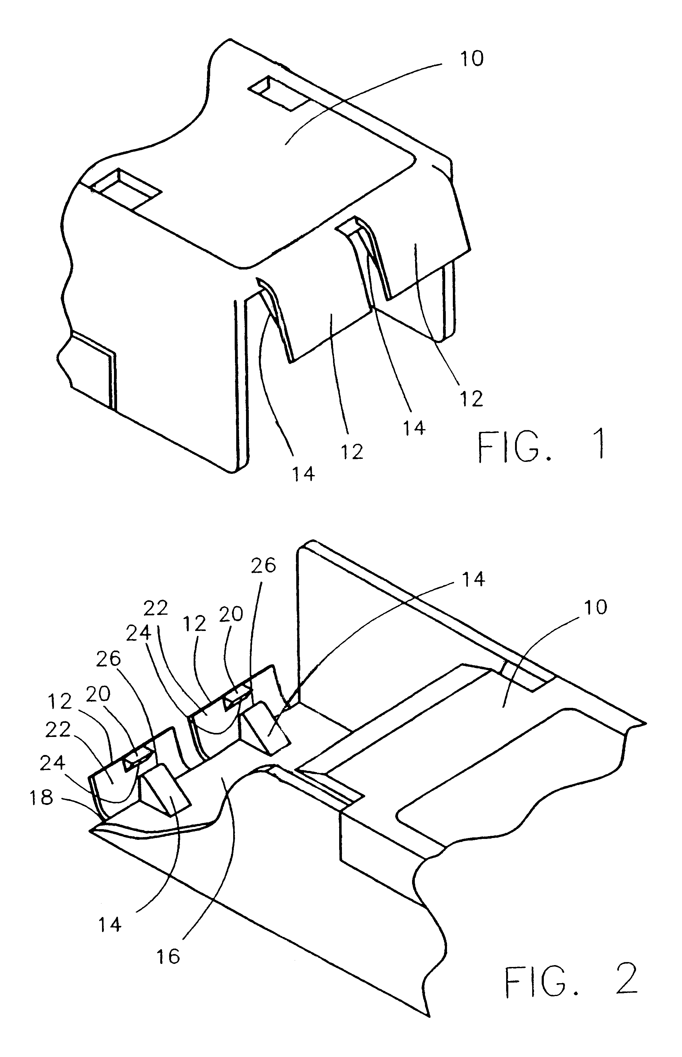
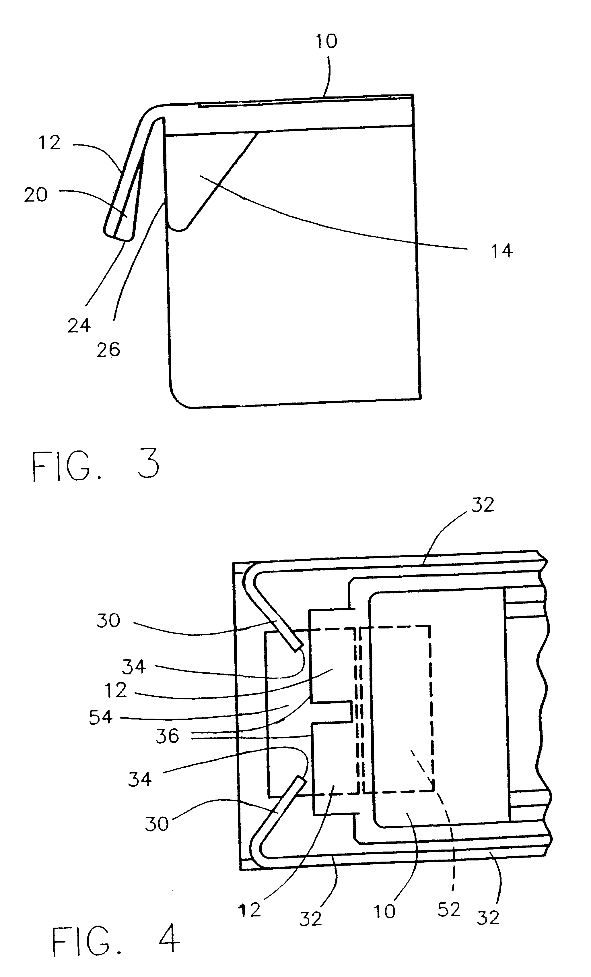
Referring initially to FIG. 1, a portion of a transceiver module chassis 10 is illustrated showing two cantilevered spring members 12 integrally molded with the transceiver module chassis 10. It is preferred that two springs 12 be incorporated into the transceiver module chassis 10 in order to balance forces and symmetry; however, any number of such springs may be used so long as the forces exerted thereon and thereby do not create a binding condition within a port (not shown) for mounting a transceiver module 10.

Due to the resilient qualities of the moldable plastic, the springs 12 are deflectable or deformable under load and resilient. As is well known by those of skill in the art of plastic part design, the thickness of the springs, the dimensions of the attachment structure, the length of the cantilevered beam, and the characteristics of the materials from which the cantilevered beam and the transceiver module chassis are made will together determine the spring force constant of...


PUM


Abstract

A spring-to-spring engagement of a kick-out spring and a secondary spring is disposed intermediate a structure supporting an electrical connector and an insertable and latchable electronic module or the like to enhance the disconnection and ejection of the module from the connector to which the module is connected. The spring-to-spring engagement insures both that adequate spring force is stored upon insertion and connection of the module and that disconnection and ejection forces are applied to the module. The forces are applied over a sufficient distance to fully displace the module from its latched position to its position of disconnection from the connectors and still provide spring force travel of the module to eject at least partially the module from the receiver or port into which the module was inserted and connected. A side benefit of the arrangement is that a high force is exerted on the module once it is unlatched for removal, and this high force will displace the module adequately to insure that the latch of the module does not relatch and to prevent removal of the module.

Description

This invention relates to the field of electronic interconnections and, more specifically, the provision of the disconnection force and disconnection displacement required for reliable and automatic disconnection for small electronic modules or the like as well as at least partial ejection thereof whenever the modules are difficult to grasp while being unlatched and removed from a host receiving device.Increasingly, computers are being connected to other computers and servers using fiber-optic cable or coaxial cable. Efficient connecting or networking of the computers and servers requires the interchangeability of transceiver modules utilized to connect the coaxial or fiber-optic cable to the electronics of a computer or server. Interchangeability of transceiver modules is necessary both to accommodate those existing differences between the electrical signals carried over coaxial cable and the light pulse signals carried on a fiber-optic cable, and then to convert the signals betwee...

Claims


Application Information

Patent Timeline
Patent Type & Authority Patents(United States)
IPC IPC(8): H01R13/633H01R13/635H01R13/64H01R13/641
CPCH01R13/635H01R13/641
Inventor BRANCH, SCOTT M.HOGAN, WILLIAM K.OLSON, JAMES E.
Owner LUMENTUM OPERATIONS LLC
Why Eureka
Try Eureka