Reservoir apparatus and auxiliary reservoir

a technology of auxiliary reservoir and reserve cylinder, which is applied in the direction of braking system, rotary clutch, fluid coupling, etc., can solve the problems of film jeopardizing the replenishment property of working fluid, high auxiliary reservoir on the master cylinder as a whole, and large mounting space of the master cylinder with the auxiliary reservoir attached thereto

Inactive Publication Date: 2003-04-22
DIESEL KIKI CO LTD
View PDF3 Cites 11 Cited by
  • Summary
  • Abstract
  • Description
  • Claims
  • Application Information

AI Technical Summary

Benefits of technology

As another form of the protruded portion, the opening portion of the connecting pipe may be disposed in such a manner as to be orthogonal to a direction of the height of the auxiliary reservoir. In that case, the entire opening portion is located at the uppermost part of a reservoir space formed within the auxiliary reservoir. Consequence, as the replenishment working fluid fills the reservoir space in the auxiliary reservoir, the entire opening portion is choked with the working fluid almost at the same time (i.e., instantaneously) on the last stage of the filling operation. Accordingly, it can be consistently avoided that the size of the opening portion of the connecting pipe is gradually reduced. Since it is considered that the film covering the opening portion, i.e., the so-called "soap bubble" is generated in a state in which the size of the connecting pipe is gradually reduced, another form of the protruded portion as mentioned is also effective.

Problems solved by technology

However, in that form, the height of the auxiliary reservoir on the master cylinder becomes high as a whole and the mounting space of the master cylinder with the auxiliary reservoir attached thereto becomes large.
As a result, he found out a fact that a film of the working fluid is formed at an opening portion of the connecting pipe which faces the inside of the auxiliary reservoir at the time of replenishment and therefore, there is such a risk that the film jeopardizes the replenishment property of the working fluid.
However, it is required for vacuum breathing to employ extra equipment such as a vacuum pump and in addition, the operation is troublesome.

Method used


Image

  • Reservoir apparatus and auxiliary reservoir
  • Reservoir apparatus and auxiliary reservoir
  • Reservoir apparatus and auxiliary reservoir

Examples


Embodiment Construction

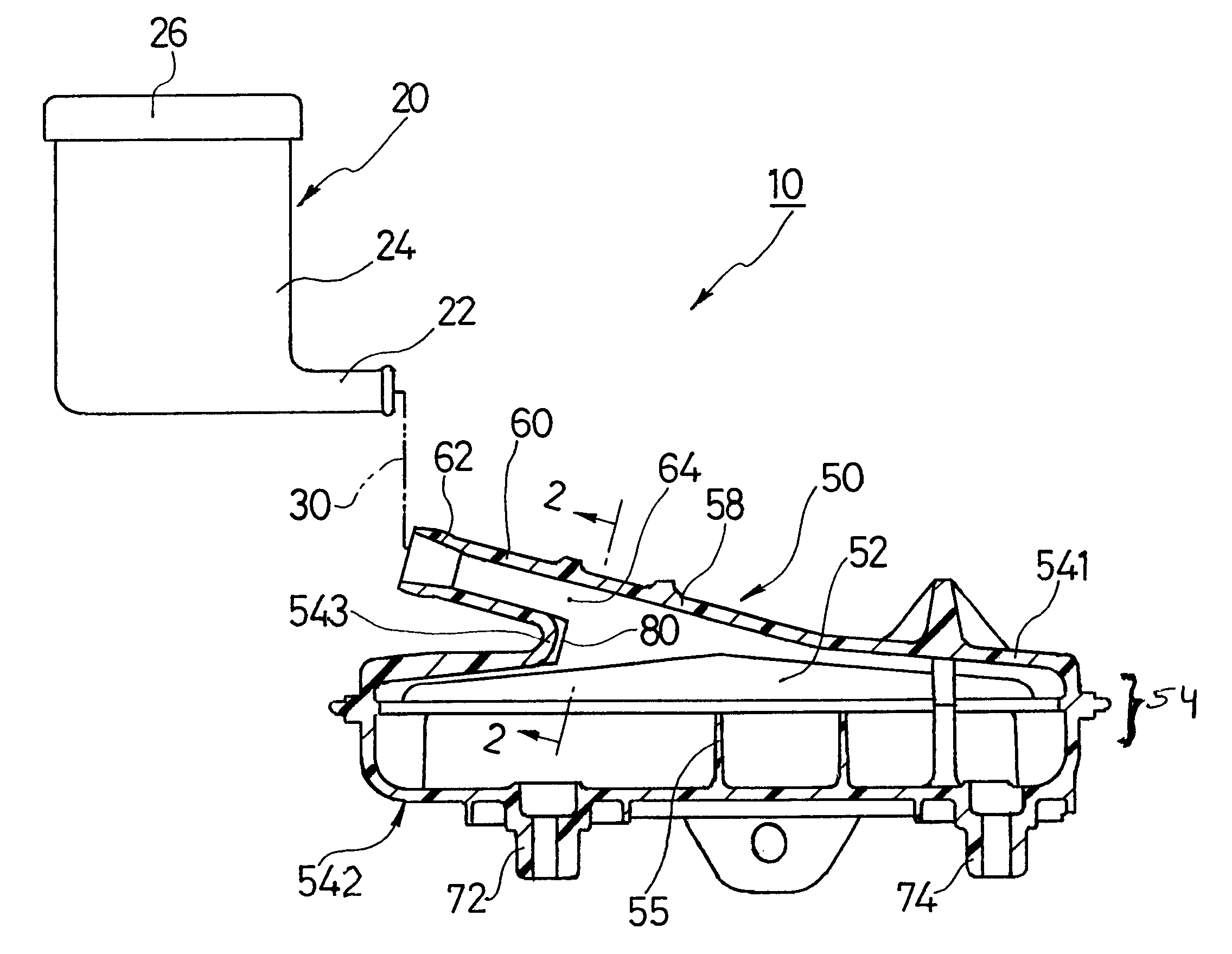
FIG. 1 shows one embodiment of the present invention in which the present invention is applied to a reservoir apparatus for use of a tandem type master cylinder and in which an auxiliary reservoir portion is shown in a sectional view. A reservoir apparatus 10 as one embodiment of the present invention comprises a main reservoir 20 arranged at a location easy to conduct the replenishing operation, and an auxiliary reservoir 50 supported on a cylinder main body of a master cylinder not shown. The main reservoir 20 comprises a container main body 24 including a piping connecting portion 22, and a cap 26 for covering an upper opening of the container main body 24. By removing the cap 26, the upper opening of the container main body 24 can serve as an inlet opening for feeding a hydraulic fluid. Since a fluid surface detector means (not shown) including a float is received in the container main body 24 of the main reservoir 20, the capacity of the main reservoir 20 is larger than that of...


PUM


Abstract

To provides a technique capable of replenishing a working fluid smoothly while employing a method for replacing an atmospheric air with the working fluid. The reservoir apparatus (10) includes a main reservoir (20) having an inlet opening for feeding a hydraulic fluid, and an auxiliary reservoir (50) connecting thereto through a piping (30). There is a diagonally extending connecting pipe (60) at the auxiliary reservoir (50). There is a recessed portion (80) at an opening portion (64) of an inner periphery of the connecting pipe (60). This recessed portion (80), when compared with the case where there is no such a recessed portion, serves to enlarge the opening portion (64) of the connecting pipe (60) and more smoothly flow the replenishment working fluid at a nearby area of the opening portion (64). By doing so, the opening portion (64) of the connecting pipe (60) can be more enlarged at the time of replenishment of the working fluid and formation of a film of the working fluid can be prevented at the opening portion (64).

Description

1. Field of the InventionThis invention relates to a reservoir technique for supplying a working fluid to a master cylinder of vehicles, and more particularly to a reservoir of the type which comprises an auxiliary reservoir located proximal or close to a master cylinder and a main reservoir having a hydraulic fluid inlet opening and connected to the auxiliary reservoir through a piping.2. Related ArtA master cylinder of vehicles essentially requires a working fluid for operating the braking system, etc. It is the reservoir apparatus which stores the working fluid. Experience teaches that work is also necessary for supplying a working fluid to the reservoir apparatus or replacing the working fluid with new one.There is known a reservoir apparatus which has been developed taking into consideration the replenishing work and replacing work of the working fluid and in which a hydraulic fluid inlet opening for the working fluid is arranged at a located where both the replenishing work an...

Claims


Application Information

Patent Timeline
Patent Type & Authority Patents(United States)
IPC IPC(8): B60T11/10B60T11/26B60T17/06B60T17/00
CPCB60T17/06B60T11/26
Inventor HONDA, YUKIHIRO
Owner DIESEL KIKI CO LTD
Why Eureka
Try Eureka