Multi-channel uniform output type transformer

Inactive Publication Date: 2003-04-29
NJ COMPONENTS CO LTD
View PDF6 Cites 42 Cited by
  • Summary
  • Abstract
  • Description
  • Claims
  • Application Information

AI Technical Summary

Problems solved by technology

In other words, even if there is any slight difference in capacity between each battery, it can lead to big power loss as a whole.
In addition to the above described problem to make the output voltage uniform, there is also a problem in the manufacture that a conductor to be used for the secondary winding must be wound a number of times corresponding to the number of output channels.
More specifically, i

Method used


Image

  • Multi-channel uniform output type transformer
  • Multi-channel uniform output type transformer
  • Multi-channel uniform output type transformer

Examples


first embodiment (

Flat Cable Belt Type)

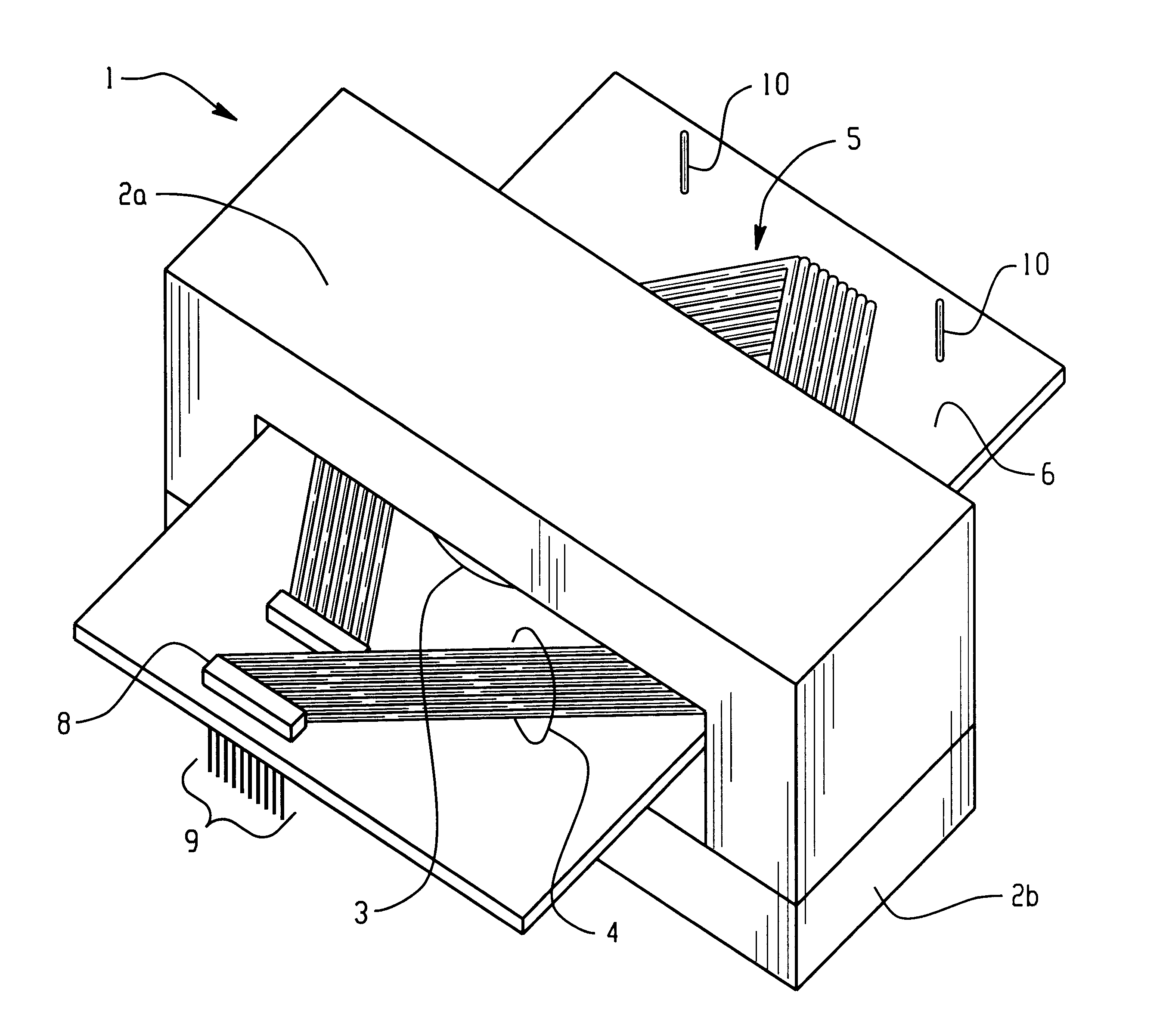
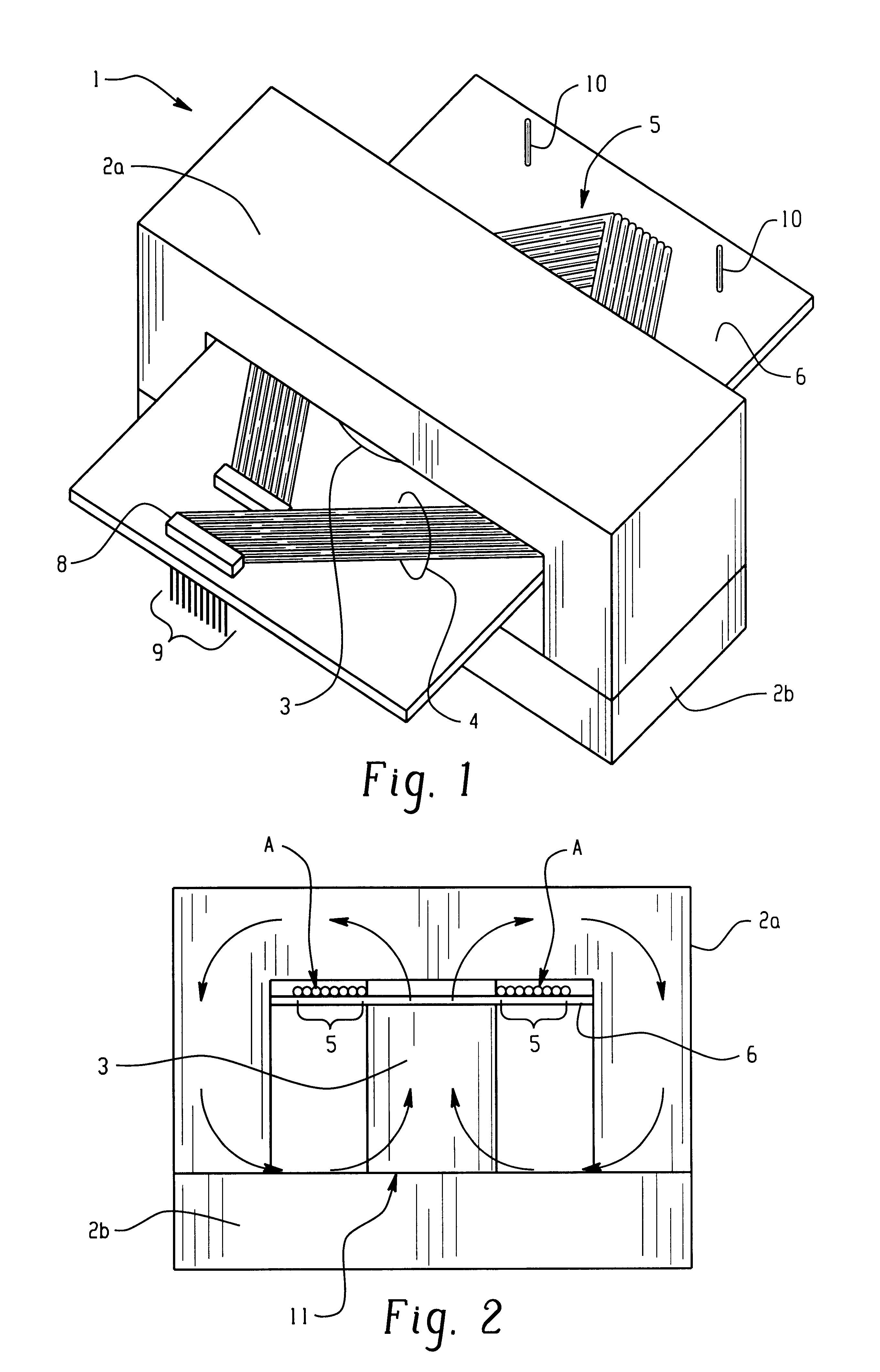
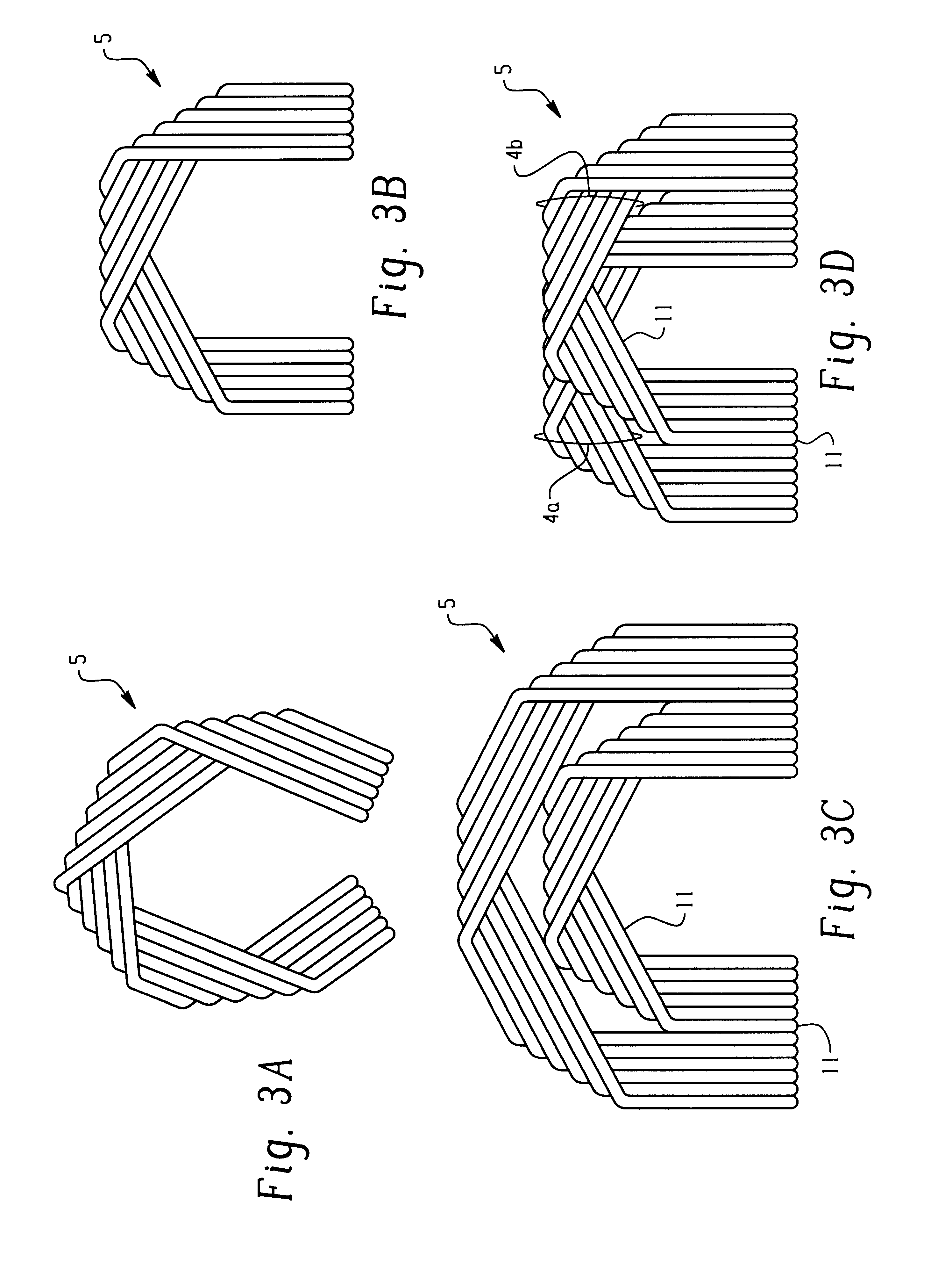
FIG. 1 is a perspective view showing an exterior appearance of a multi-channel uniform output type transformer (hereinafter, referred to as "transformer") according to an embodiment of the present invention as viewed from the upper part in front. The secondary winding is a flat cable belt 4 including covered conductor for the output system, and this flat cable belt 4 is wound, for a turn, round a winding shaft portion 3 of EI type cores 2a and 2b to form a flat loop member 5. This flat loop member 5 is arranged in the form of a plane on a printed circuit substrate 6 parallel to a plane orthogonal to the winding shaft portion 3 by folding the flat cable belt 4 in the same direction a plurality of number of times. In this respect, the number of turns of the secondary winding is not limited to one turn, but can be appropriately changed in accordance with the output voltage.

An end portion of the flat cable belt 4 is collectively pressed by a flat cable connector 8 f...

second embodiment (

Sheet Coil Type)

FIGS. 5A and 5B are schematic structural views showing a multi-channel uniform output type transformer 1b using a sheet coil according to a second embodiment of the present invention. FIG. 5A is a perspective view showing an external appearance of this transformer 1b as viewed from the upper part in front, and FIG. 5B is a sectional view taken on an alternate long and short dash line a in FIG. 5A as viewed from the front.

This transformer 1b is a sheet coil comprising a coil formed by a printed circuit in which both a primary winding and a secondary winding are formed on a substrate, and is constituted by substantially orthogonally intersecting each sheet coil with the core winding shaft to stack and arrange. In the example shown, one each of secondary sheet coils 50a and 50b is stacked above and below one primary sheet coil 40, and each of the sheet coils 40, 50a and 50b is caused to substantially orthogonally intersect with the winding shaft portion 3 of the EE type...


PUM


Abstract

A multi-channel output type transformer for outputting uniformly balanced voltage among multiple output channels. The transformer comprising a primary winding and a secondary winding that is wound round a winding shaft portion of a core. The secondary winding of the transformer is a flat cable belt comprising covered conductors corresponding to the number of output channels. The cable belts are arranged in parallel. A plane loop is formed by appropriately folding the flat cable belt, and the plane loop member is arranged to as to substantially orthogonally intersect the winding shaft of the core.

Description

1. Technical Field of the InventionThe present invention relates to a transformer to be applied to a switching power unit for charging a battery group in, for example, an electric automobile, and more particularly to a multi-channel uniform output type transformer for obtaining output at the same level from a multiplicity of secondary windings.2. Description of the Prior ArtIn, for example, the electric automobile, a power source obtained by series connecting as many secondary batteries as 200 or more is used as a driving power source. It is not simple to uniformly and efficiently charge these many batteries, but concerning a charging system, various technical development has been pursued. As one of them, such a charging system as shown in FIG. 11 has been proposed.According to this system, the multi-channel uniform output type transformer 1 is used for a charging apparatus, and each channel output 31 of the transformer is connected in parallel to each battery 21 of a series battery...

Claims


Application Information

Patent Timeline
IPC IPC(8): H01F27/28H01F27/00H01F27/40H01F19/00H01F27/30H01F30/00H01F30/04H02M3/28
CPCH01F27/40H01F27/2804
Inventor NAKAO, FUMIAKIOHTA, SATOSHIKITAOKA, MIKIOYAMADA, KATSUOSAKAMOTO, HIROSHI
Owner NJ COMPONENTS CO LTD
Why Eureka
Try Eureka