Co-extruded tubing for an off-axis ink delivery system

a technology of co-extrusion and ink, which is applied in printing and other directions, can solve the problems of increasing the fatigue of the tube, reducing the lifetime of the tube, and inconvenient operation

Inactive Publication Date: 2003-05-06
HEWLETT PACKARD DEV CO LP
View PDF7 Cites 19 Cited by
  • Summary
  • Abstract
  • Description
  • Claims
  • Application Information

AI Technical Summary

Benefits of technology

FIG. 2 is an enlarged sectional perspective view taken along the line 2--2 of FIG. 1, depicting the fluid transport conduit comprising at least two layers

Problems solved by technology

This tubing arrangement has led to a number of problems, due in large part, to the effects of tube bending during reciprocation of the pen.
Such bending, for example, will often produce an unacceptably high stress on the tube, increasing tube fatigue, and correspondingly decreasing the lifetime of the tube.
In addition, bending of the tubes may result in an undesirably high torque on the pen carriage, increasing the power required to drive the pen.
Further, because the bending of tubes requires a significant amount of clearance, the use of off-axis ink supplies has resulted in a significant increase in the printer's size.
The latter problem is particularly troublesome where a multi-color pen is employed, it being necessary to run a plurality of tubes (one for each color) between the reservoir and the reciproc

Method used


Image

  • Co-extruded tubing for an off-axis ink delivery system
  • Co-extruded tubing for an off-axis ink delivery system

Examples


Embodiment Construction

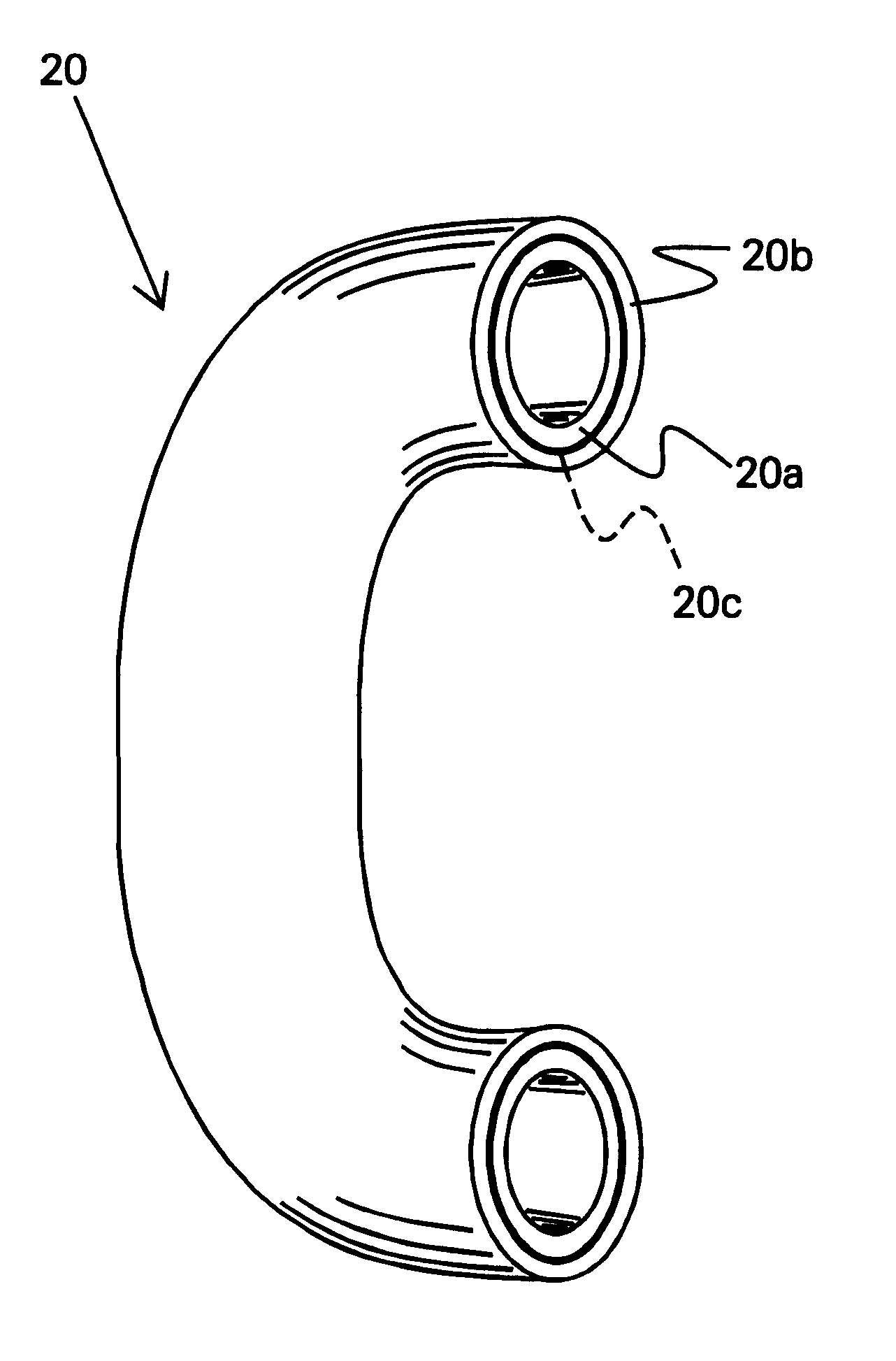
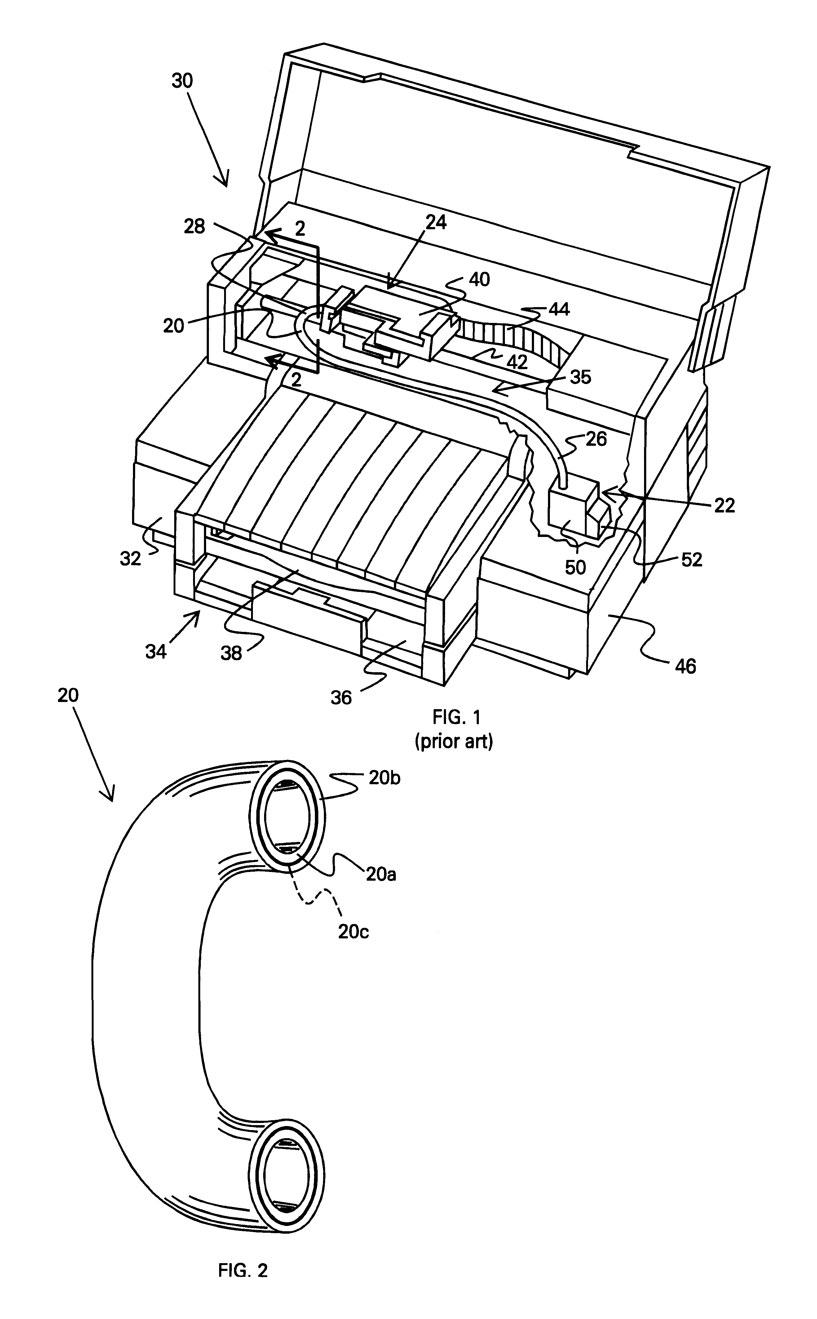
FIG. 1 illustrates an embodiment of a flexible conduit 20, constructed in accordance with the present invention, which may be used to convey or transport a fluid therethrough from a first location 22 to a second location 24. The conduit or tube 20 has a first end 26 for receiving fluid at the first location 22, and a second end 28 for delivering fluid to the second location 26. It is apparent that the conduit system 20 may be used in a variety of different applications requiring a flexible conduit to couple together two remote locations. In particular, the conduit 20 is well suited for applications having the two locations 22, 24 moving relative to one another. For example, the conduit 20 may be useful in hydraulic applications, or various robotic applications requiring fluid conveyance, such as chemical sprays, paint sprays, coolant or lubricating systems, and the like.

One particularly useful implementation for discussing the characteristics of conduit is an ink jet printing mechan...


PUM


Abstract

A fluid transport conduit for conveying ink-jet ink from a reservoir to a printhead in an ink-jet printer is provided. The fluid transport conduit comprises at least one inner layer, such as high density polyethylene, cyclic olefin copolymer, or polypropylene homopolymer, that is flexible and is a barrier to liquids, and at least one outer layer, such as nylon or polyvinyl alcohol, that is a barrier to air and is softer, or more compliant, than the inner layer, with the inner layer bonded to the outer layer. The two layers are advantageously co-extruded to form the fluid transport conduit.

Description

The present invention is directed to ink-jet printers and, more particularly, to ink-jet printers employing an off-axis ink delivery system for replenishing on-axis print cartridges with ink.In a conventional ink jet printer, ink is deposited on record media such as paper via a disposable pen, the pen being mounted on a carriage for reciprocation across the paper's face. Ink is ejected through the pen's printhead, the printhead being connected to a volume of ink which is stored in a reservoir onboard the pen. When the ink reservoir is depleted, the pen is removed from the carriage, discarded, and replaced with a new pen. An example of such a pen is disclosed in U.S. Pat. No. 4,771,295, which is entitled "Thermal Ink Jet Pen Body Construction Having Improved Ink Storage and Feed Capability", and which is commonly owned herewith. The disclosure of that patent is incorporated herein by this reference.In order to extend the useful life of ink jet pens, several off-axis ink supply approa...

Claims


Application Information

Patent Timeline
IPC IPC(8): B41J2/175
CPCB41J2/17509B41J2/175
Inventor SHIBATA, ALANBIGGS, ALANNGUYEN, LAP THAIKNIFFIN, JOHN MICHAELNASH, PAUL L.LIU, YIMELLO, GERALD A.TEE, AH CHONG JOHNNYLONGUST, TIMOTHY A.ROMAN, JUSTIN M.
Owner HEWLETT PACKARD DEV CO LP
Why Eureka
Try Eureka