
Adjustable gate structure

Inactive Publication Date: 2003-05-13
LACKEY JR JOE
View PDF8 Cites 18 Cited by
  • Summary
  • Abstract
  • Description
  • Claims
  • Application Information

AI Technical Summary

Benefits of technology

It is an object of this invention to provide an adjustable gate which is adjustable over a set horizontal width which is straight-forward and easy to assemble.
Yet another object of the invention is to produce a gate which is sturdy, yet relatively light-weight and affords ease in handling.
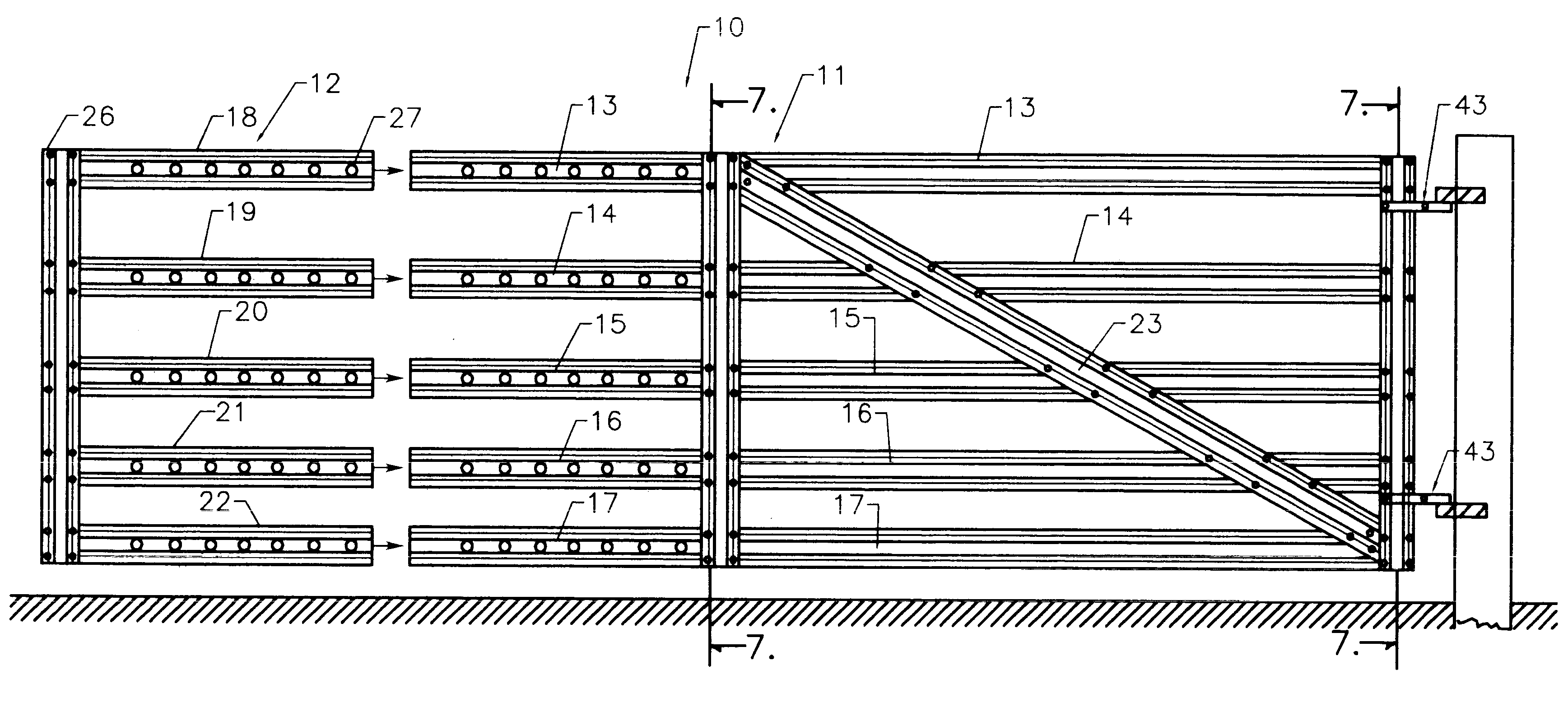
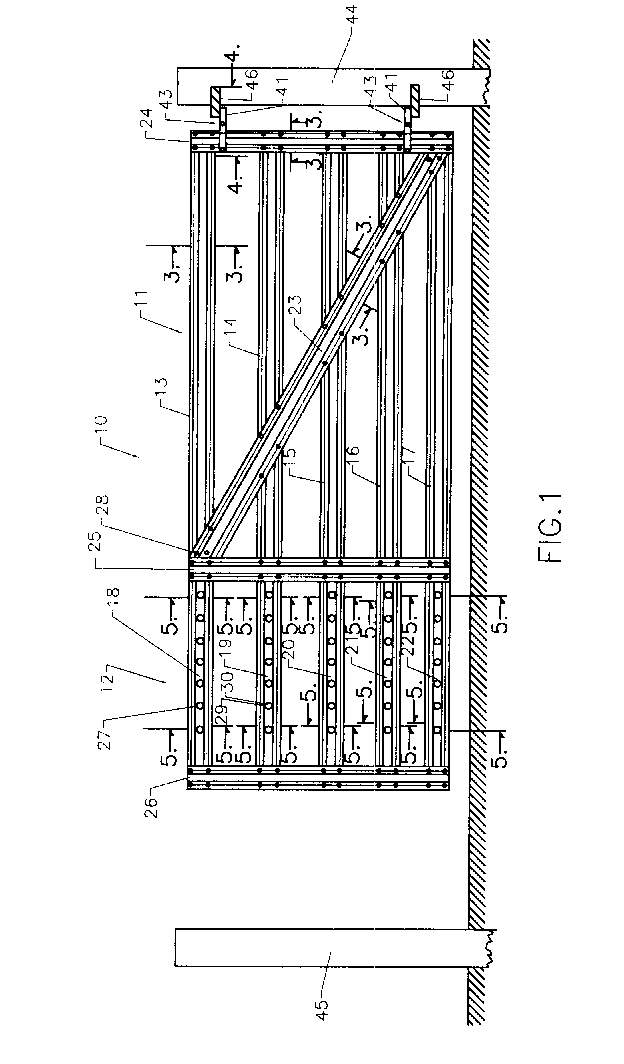
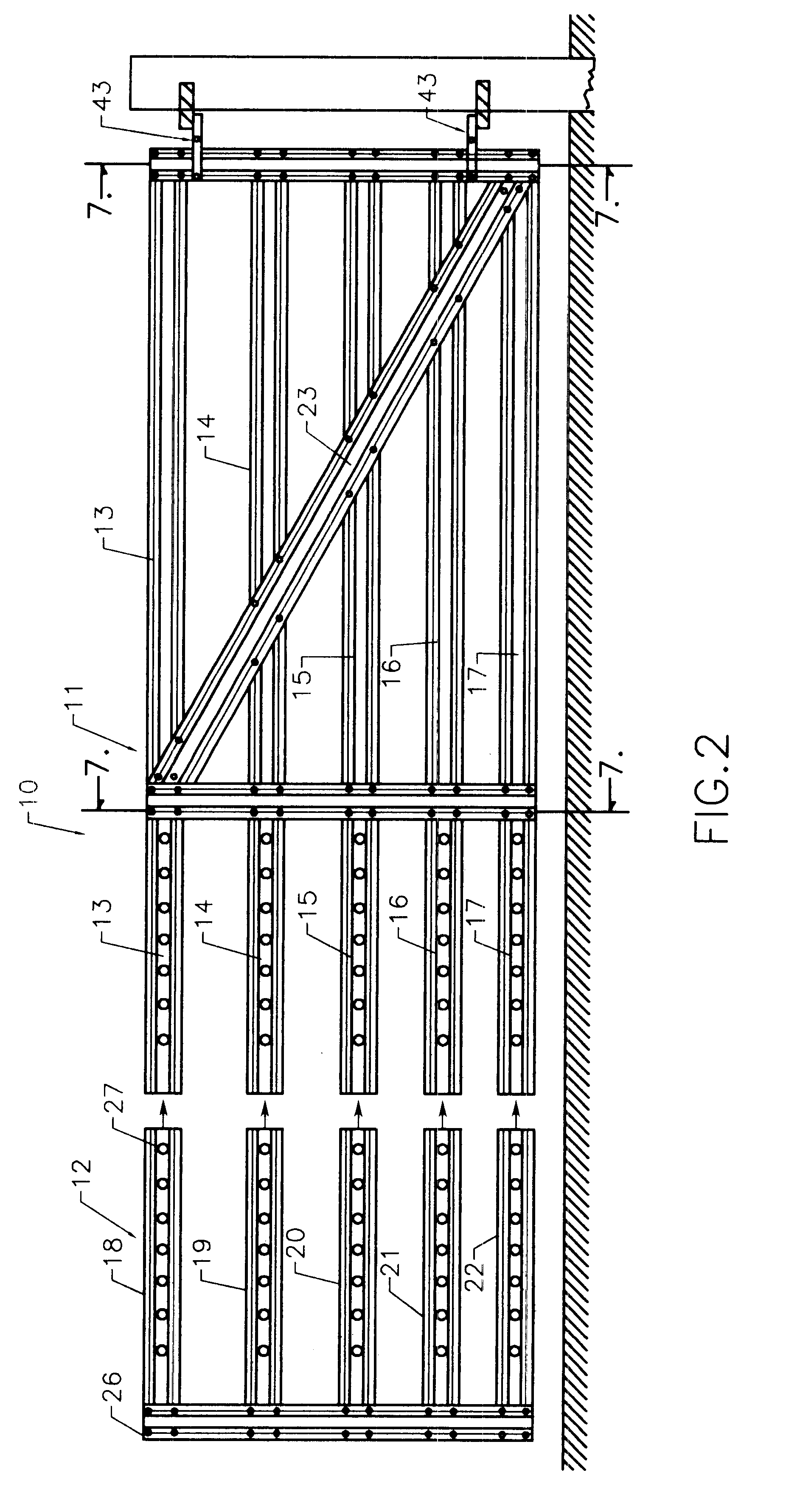
As the connection between each end of the adjustable extension unit 12 and the frame unit 11 is the same, only one will be described. Panel 18 is placed upon panel 13 in an overlapped position whereby two sets of apertures 27 on panel 18 coincide with corresponding apertures 27 on panel 13. Each pair of apertures 27 should be spaced as far apart as possible to maintain rigidity while allowing the adjustable extension unit 12 to be extended or reduced to its desired feet or inches. As best illustrated in FIG. 5, the interposed panels 18 and 13 are secured through each set of apertures 27 by a 3 / 8" bolt 30 and washer 29 on panel 18 shown in FIG. 8. Shown in FIG. 9, washer 29 and wing nut 35 tighten the bolt 30 after it passes through panel 13. Stainless steel bolts, washers and wing nuts are recommended for durability. In this manner, when all five pair of the panels are connected one can expand or reduce the horizontal width of gate 10.
As best illustrated in FIG. 5, the interposed panels 18 and 13 (as well as 19-14, 20-15, 21-16 and 22-17) are secured through each set of selected apertures 27 by a 3 / 8" bolt 30 and washer 29 shown in FIG. 8. As shown in FIG. 9, washer 29 and wing nut 35 tighten the bolt 30 after it passes through aperture 27. In this manner, when all five pair of the panels are interposably connected one can expand or reduce the horizontal width of gate 10.

Problems solved by technology

In many instances, the exact width of a gate opening in a fence is not readily attainable before the fence is constructed.
These gates require complex construction and are not unlimited in extending their horizontal widths in conventional ranch type fence construction.

Method used


Image

  • Adjustable gate structure
  • Adjustable gate structure
  • Adjustable gate structure

Examples


Embodiment Construction

The gate's main frame unit 11 is held in an upright position. The adjustable extension unit 12 is placed against frame unit 11 at the desired spacing of the apertures 27 in an overlapped position. Panels 18, 19, 20, 21 and 22 are placed in interposed positions upon panels 13, 14, 15, 16 and 17 respectively.

Two pair of apertures 27 opposing each other on each set of interposed panels should coincide evenly. Each chosen pair of apertures 27 should be spaced as far apart as possible to maintain rigidity of the extension unit 12.

As best illustrated in FIG. 5, the interposed panels 18 and 13 (as well as 19-14, 20-15, 21-16 and 22-17) are secured through each set of selected apertures 27 by a 3 / 8" bolt 30 and washer 29 shown in FIG. 8. As shown in FIG. 9, washer 29 and wing nut 35 tighten the bolt 30 after it passes through aperture 27. In this manner, when all five pair of the panels are interposably connected one can expand or reduce the horizontal width of gate 10.

ALTERNATIVE EMBODIMEN...


PUM


Abstract

An improved adjustable gate structure which is suitable for a fence with an opening therein which is too wide or narrow for a conventional gate, the gate's horizontal width can be increased or reduced by simple mechanical adjustments. The preferred embodiment of this gate consists of a main frame with a plurality of long horizontal panels of equal length affixed parallelographically to a vertical panel approximately 5' in height and an extension frame with the same plurality of short horizontal panels of equal length also affixed to a panel approximately 5' tall. All of the panels are spaced equally in relation to the ground. Apertures are punched or drilled equidistantly in the short panels and the distal ends of the long panels. The method to join the two frames at a pre-determined width is to interpose the short panels upon the distal ends of the long panels, thereby aligning the apertures with one or two apertures being secured on every set of panels with fasteners. Thus, the newly expanded or reduced width gate is made ready to be swingably upon its mounting post.

Description

This invention relates to a gate whose horizontal width can be mechanically varied to properly fit the opening between two terminal fence posts.BACKGROUND OF THE INVENTION AND DISCUSSION OF PRIOR ARTIn many instances, the exact width of a gate opening in a fence is not readily attainable before the fence is constructed. This leaves the fence builder with the option of waiting to install a gate until a custom or standard manufactured gate can be obtained, or trying to fit a gate into the opening.Several types of adjustable gates have been proposed, i.e. U.S. Pat. No. 3,290,014 to Stapleton (1966) and U.S. Pat. No. 5,716,041 to Groves (1998). These gates require complex construction and are not unlimited in extending their horizontal widths in conventional ranch type fence construction.SUMMARY OF THE INVENTION OBJECTS AND ADVANTAGESThe adjustable gate of this invention is suitable for use with a fence, or other fixed structure. It employees five horizontal panels or slats which are at...

Claims


Application Information

Patent Timeline
IPC IPC(8): E06B11/00E06B11/02
CPCE06B11/02
Inventor LACKEY, JR., JOE
Owner LACKEY JR JOE
Learn More