Auto-calibrating voltage regulator with dynamic set-point capability

a voltage regulator and dynamic set-point technology, applied in the direction of electric variable regulation, process and machine control, instruments, etc., can solve the problems of consuming more power than necessary and reducing efficiency

Inactive Publication Date: 2003-05-20
INTEL CORP
View PDF12 Cites 18 Cited by
  • Summary
  • Abstract
  • Description
  • Claims
  • Application Information

AI Technical Summary

Problems solved by technology

This reduces the efficiency since the load line and offset voltage are usually non-optimal f...

Method used


Image

  • Auto-calibrating voltage regulator with dynamic set-point capability
  • Auto-calibrating voltage regulator with dynamic set-point capability
  • Auto-calibrating voltage regulator with dynamic set-point capability

Examples


Embodiment Construction

A method for operating a voltage regulator is disclosed which dynamically adjusts the load line and offset voltage. In the following description, numerous specific details are set forth such in order to provide a thorough understanding of the present invention. It will be apparent to one skilled in the art that the present invention may be practiced without these details. In other instances, well-known circuits, such as voltage regulator circuits, have not been set forth in detail in order not to unnecessarily obscure the present invention.

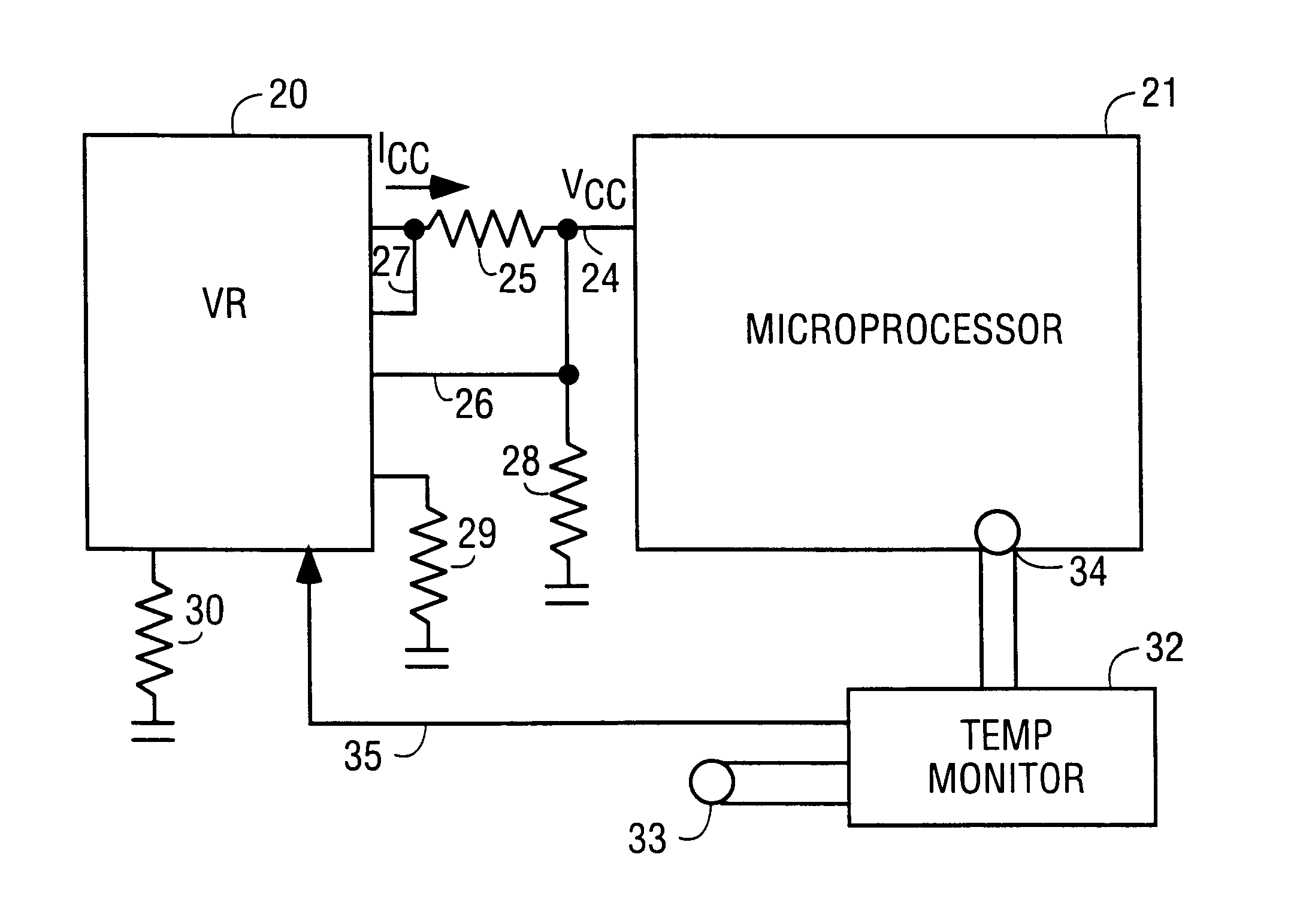
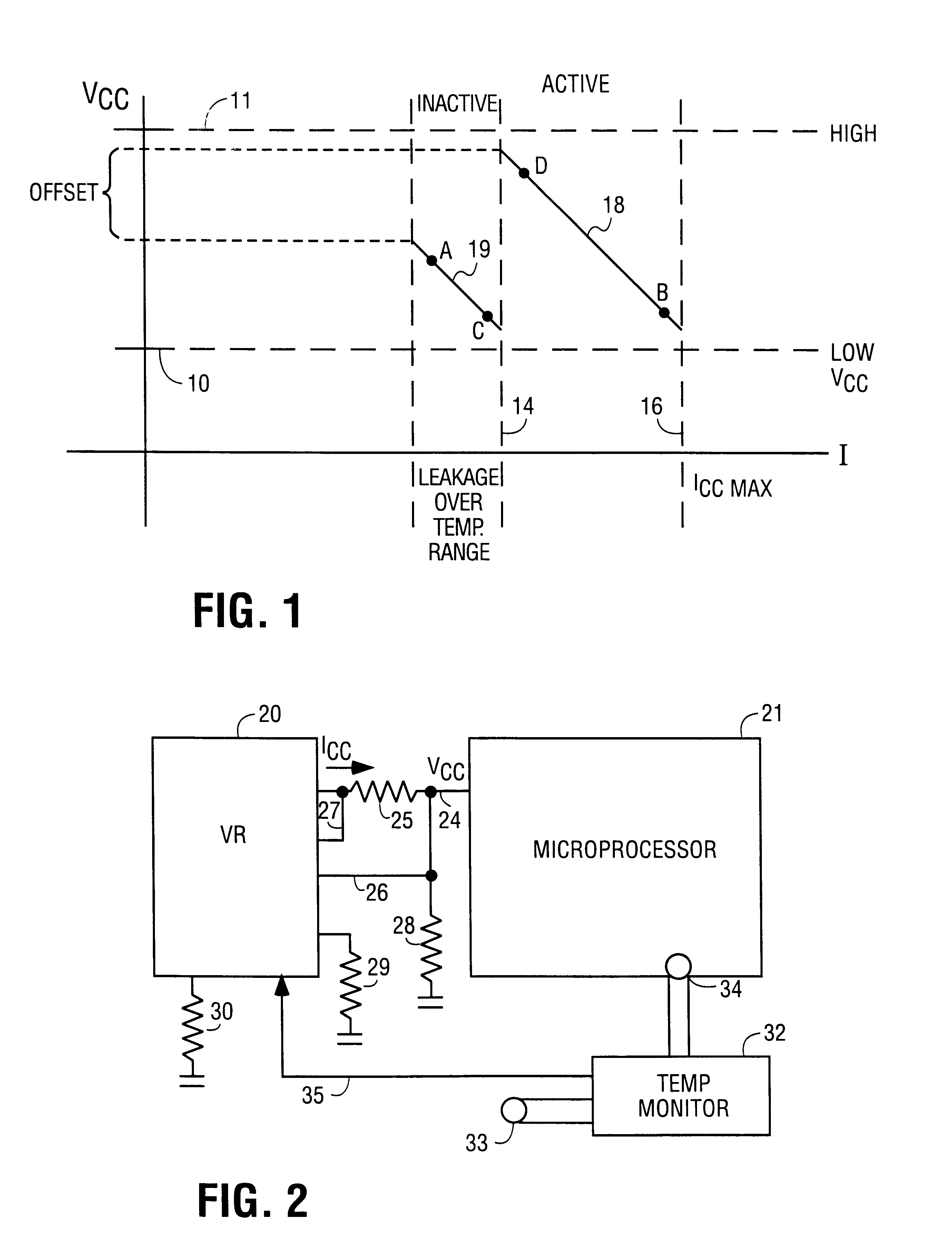
Referring to FIG. 1, typical load lines 18 and 19 for a microprocessor are illustrated. The dotted line 10 represents the lowest Vcc that the microprocessor should operate under and the line 11 shows the maximum Vcc for the microprocessor. During the microprocessor's active state, shown between the vertical lines 14 and 16, load line 18 is followed by the voltage regulator. This load line begins slightly above line 10 and ends slightly below line ...


PUM


Abstract

A voltage regulator is described which uses external resistors to set a load line and offset. During initial operation and also during normal operation the load line and offset are reset by placing, for instance, the microprocessor in a high active state, low active state and in a sleep mode. By dynamically changing the load line and offset voltage, minimum current is drawn thus extending battery life.

Description

1. Field of the InventionThe invention relates to the field of power supplies and voltage regulators for microprocessors and the like.2. Prior Art and Related ArtVoltage regulators sometimes use external resistors to assure a predetermined load line and offset voltage. For instance, the set-points assure that at low activity during an active mode, Vcc approximates the maximum power supply voltage for the microprocessor, and at maximum current load the regulator provides the minimum acceptable Vcc to the microprocessor. The resistors also provide the offset potential that allow the correct voltage for sleep modes to compensate for leakage over the operating temperature range of the microprocessor.These resistors are often selected based on the worse case part. As a practical matter, a voltage regulator for a given platform may be tuned to the highest frequency part that will be used in that platform. This reduces the efficiency since the load line and offset voltage are usually non-o...

Claims


Application Information

Patent Timeline
IPC IPC(8): G05F1/10G05F1/56
CPCG05F1/56
Inventor HORIGAN, JOHN W.GILBRIDE, DANIEL F.NGUYEN, DON J.
Owner INTEL CORP
Why Eureka
Try Eureka