Current carrying assembly for a circuit breaker

a current carrying assembly and circuit breaker technology, applied in circuit-breaking switches, circuit-breaking switches for excess currents, contacts, etc., can solve the problems of limited space available for a spring relative to each blade, relatively large quantity of molten metal and/or plasma circulating, etc., to improve the available volume, improve the shape, and reduce the spring rate

Inactive Publication Date: 2003-05-27
SQUARE D CO
View PDF7 Cites 16 Cited by
  • Summary
  • Abstract
  • Description
  • Claims
  • Application Information

AI Technical Summary

Benefits of technology

More specifically, it is an object of the invention to provide a breaker design in which the blade springs of larger size can be utilized in order to increase the available volume, allow for better shape in a relatively larger spring having more desirable characteristics such as lower spring rate, lower stress concentration factors, and the like. In addition, the springs, when somewhat larger are able to bend enough to provide enough independent force to each blade of the multiple blade assembly, so as to compensate for differences in wear and in manufacturing variables and tolerances commonly encountered in such assemblies.
Another object of the invention is to provide a protective device for protecting the blade springs both from materials that may be ejected during high-level short circuits, as well as from excessive heat transfer during high in-rush current conditions.

Problems solved by technology

However, because the blades are spaced in relatively close parallel alignment, the space available for a spring relative to each blade is limited.
In addition, during high-level short circuits there can be a relatively large quantity of molten metal and / or plasma circulating in proximity to the blade springs.

Method used


Image

  • Current carrying assembly for a circuit breaker
  • Current carrying assembly for a circuit breaker
  • Current carrying assembly for a circuit breaker

Examples


Embodiment Construction

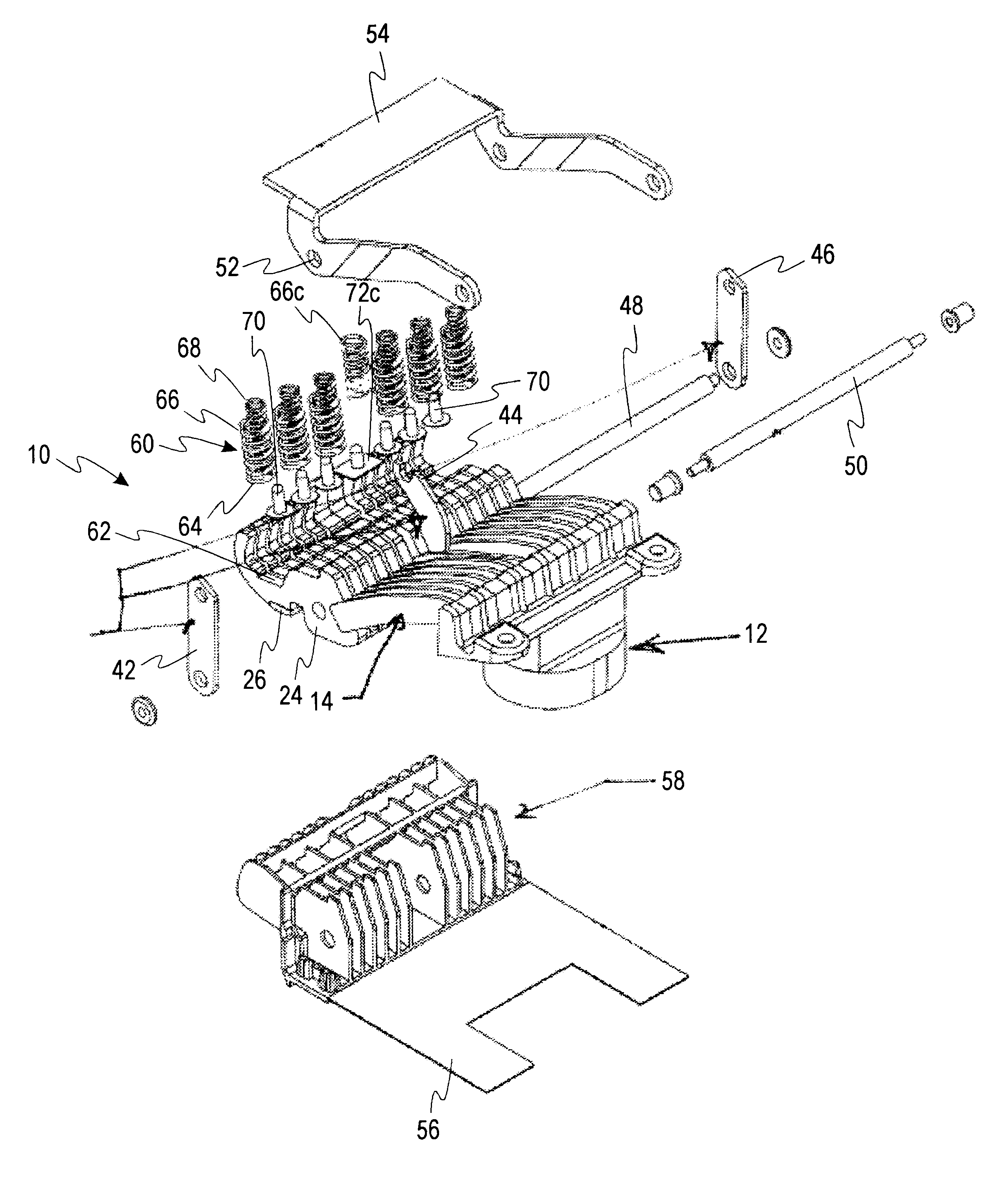
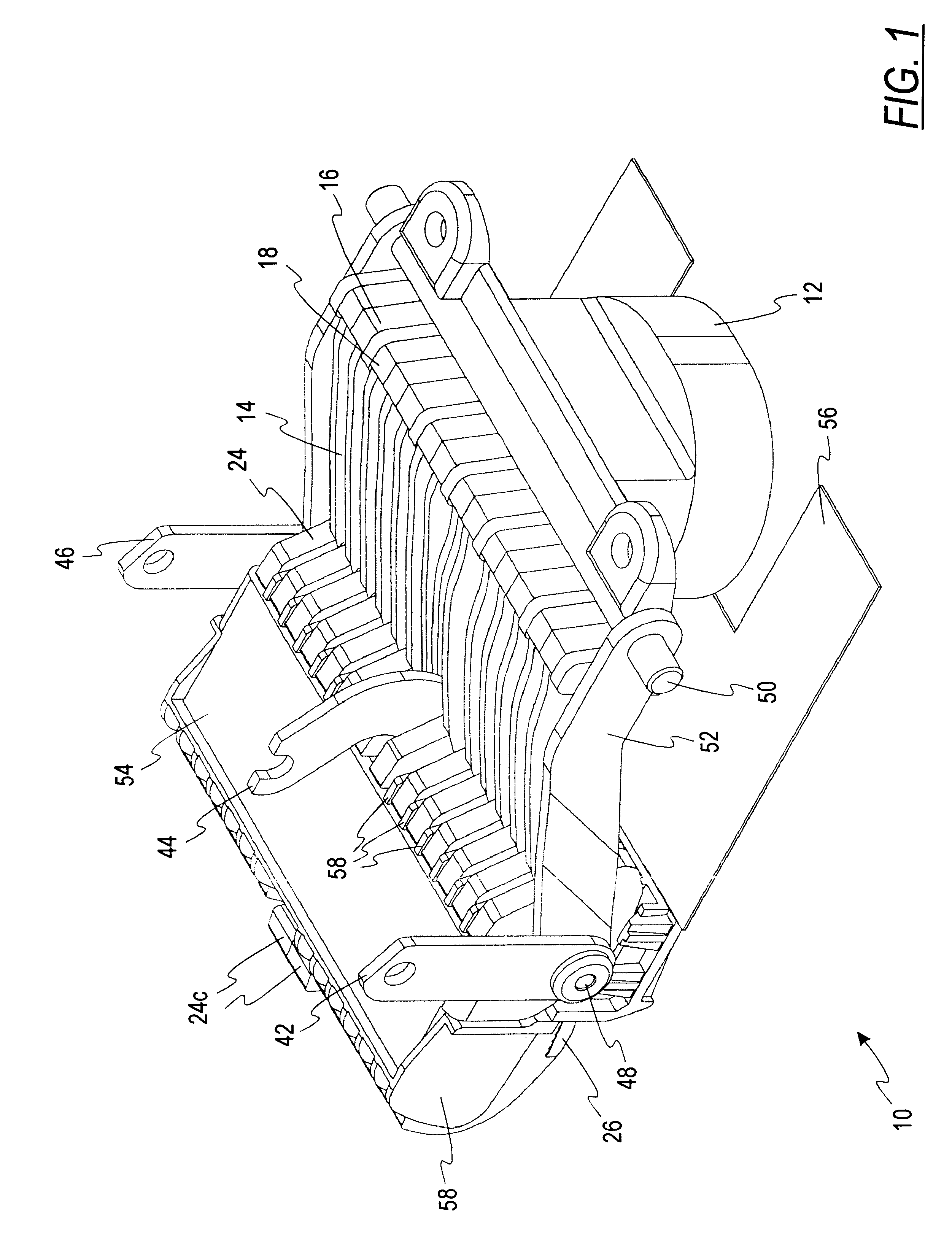
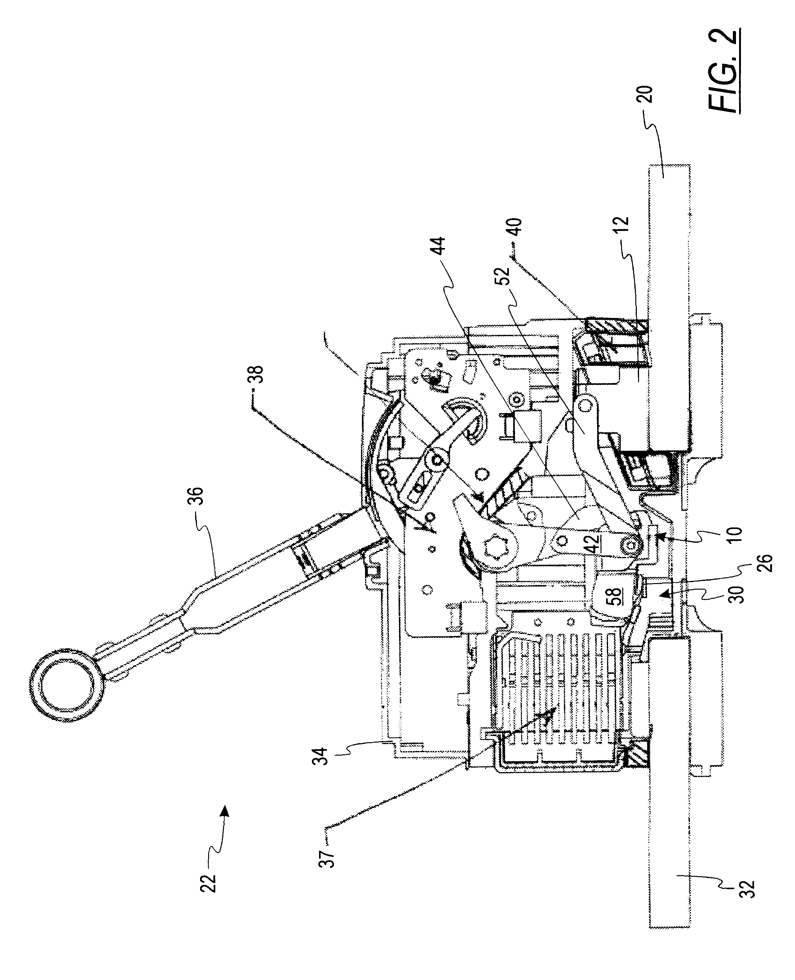
Referring now to the drawings, FIG. 1 shows a perspective view of a an assembled moveable contact assembly 10 in accordance with one embodiment of the invention. The assembly 10 includes a current transformer (CT) terminal 12, which is conductively coupled to a plurality of current carrying elements 14 which typically comprise so-called pigtails or braids, that is, braided copper conductors. These copper conductors are brazed or otherwise attached at one end thereof to solid copper and / or silver terminal elements 16, 18 which are brazed or otherwise affixed in electrically conductive contact with the casting which makes up the CT terminal 12 to establish conductive contact therewith. Referring briefly to FIG. 2, the CT terminal 12 is in turn securely fastened by bolting or other suitable means to one of the main current-carrying terminals 20 of the circuit breaker assembly 22 of which the moveable contact assembly is in part.

Referring to FIGS. 1 and 3, opposite ends of the current c...


PUM


Abstract

A blade assembly for use in a circuit breaker, the blade assembly comprising a plurality of blades, including one or more pairs of adjacent side-by-side blades having coplanar contact surfaces and coplanar bearing surfaces, at least one set of blade springs, each having one end in operative contact with the bearing surface of each of a pair of adjacent side-by-side blades, the at least one set of blade springs comprising at least one compression spring.

Description

This invention is directed generally to the field of devices for making and breaking electrical contacts in relatively high voltage environments and more particularly to an improvement in a current carrying assembly for a circuit breaker.While the current invention may find other uses, such as in switches, contactors, connectors, and the like, the invention will be described herein with reference to a circuit breaker for relatively high voltage applications. The specific circuit breaker described herein is of the type generally known as a hybrid ICL circuit breaker. One such circuit breaker is made by Schneider Electric / Square D Company under the designation PROXIMA.TM. C5.In such circuit breakers, a number of blades in a moveable pole or blade assembly are arranged to make and break contact with a fixed contact in order to close or open the circuit between the two terminals of the breaker. In order to assure good contact pressure when the breaker is closed, one or more springs are ...

Claims


Application Information

Patent Timeline
Patent Type & Authority Patents(United States)
IPC IPC(8): H01H1/22H01H1/12
CPCH01H1/226H01H1/225
Inventor MAULANDI, AYMON A.FABER, TIMOTHY R.AUREYRE, LAURENTWOODSON, CAMERON L.
Owner SQUARE D CO
Why Eureka
Try Eureka