Spoke mounted drive hub for a cycle and system for propulsion therefore

a technology of drive hubs and bicycles, which is applied in the direction of bicycles, folding cycles, transportation and packaging, etc., can solve the problems of complicated installation of specialized hubs or wheels, failure to have considered or suggested an easily mounted drive hub, and inability to meet the requirements of off-the-shelf bicycle compatibility, etc., to achieve convenient installation, reliable operation, and low cost.

Inactive Publication Date: 2003-06-03
SIMONS DENNIS R
View PDF19 Cites 37 Cited by
  • Summary
  • Abstract
  • Description
  • Claims
  • Application Information

AI Technical Summary

Benefits of technology

Unlike the prior art, the present invention provides an aftermarket motorized assist system for bicycles or the like which is easily installed by a novice, reliable in operation, inexpensive to purchase and maintain, and safe and easy to operate.
Lastly, it is an object of the present invention to provide a method and system for converting a bicycle to provide motorized assist which is easy to operate, install, and maintain.

Problems solved by technology

As will be shown below, prior art linkages have include friction drives which directly engaged the tread of the wheel, as well as specialized hubs or wheels which were either complicated installation, expensive or limited in their compatibility with off-the-shelf bicycles, or unreliable in their use.
Nonetheless, the prior art would appear to have failed to have contemplated or suggested an easily mounted drive hub designed to interface with an off-the-shelf spoked wheel on a bicycle, which is inexpensive in manufacture, quickly and securely mounted to the wheel without special tools or measurements, and compatible with different sized wheels.

Method used


Image

  • Spoke mounted drive hub for a cycle and system for propulsion therefore
  • Spoke mounted drive hub for a cycle and system for propulsion therefore
  • Spoke mounted drive hub for a cycle and system for propulsion therefore

Examples


Embodiment Construction

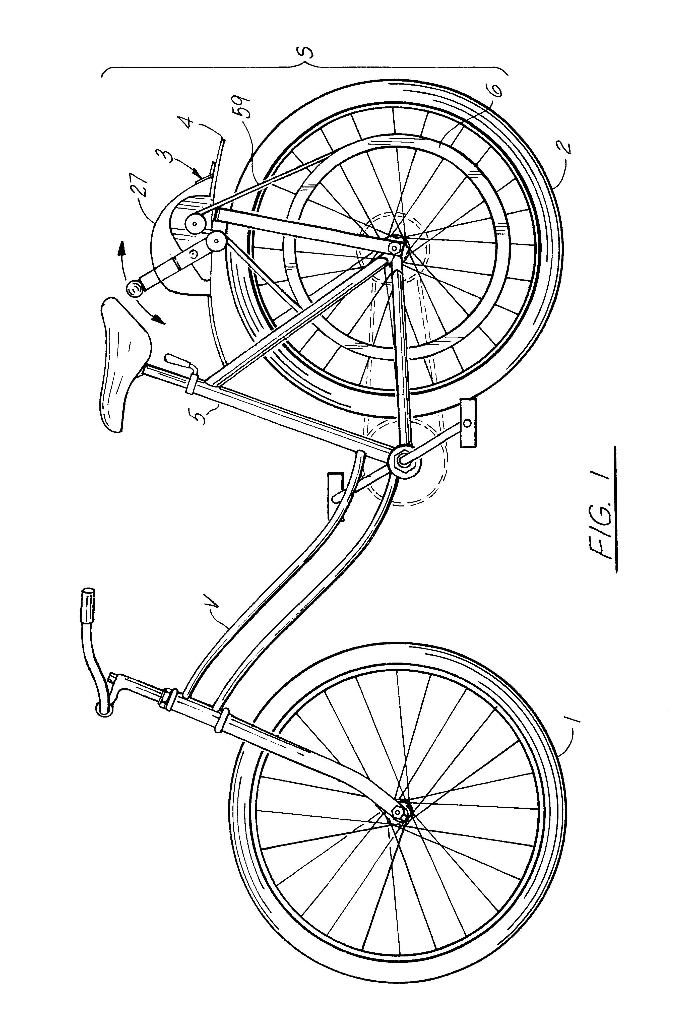
Continuing with FIG. 1 of the drawings, the system S of the present invention is configured to motorize a wheeled vehicle V, the preferred embodiment of the present invention configured to be utilized in conjunction with a bicycle having front 1 and rear 2 wheels.

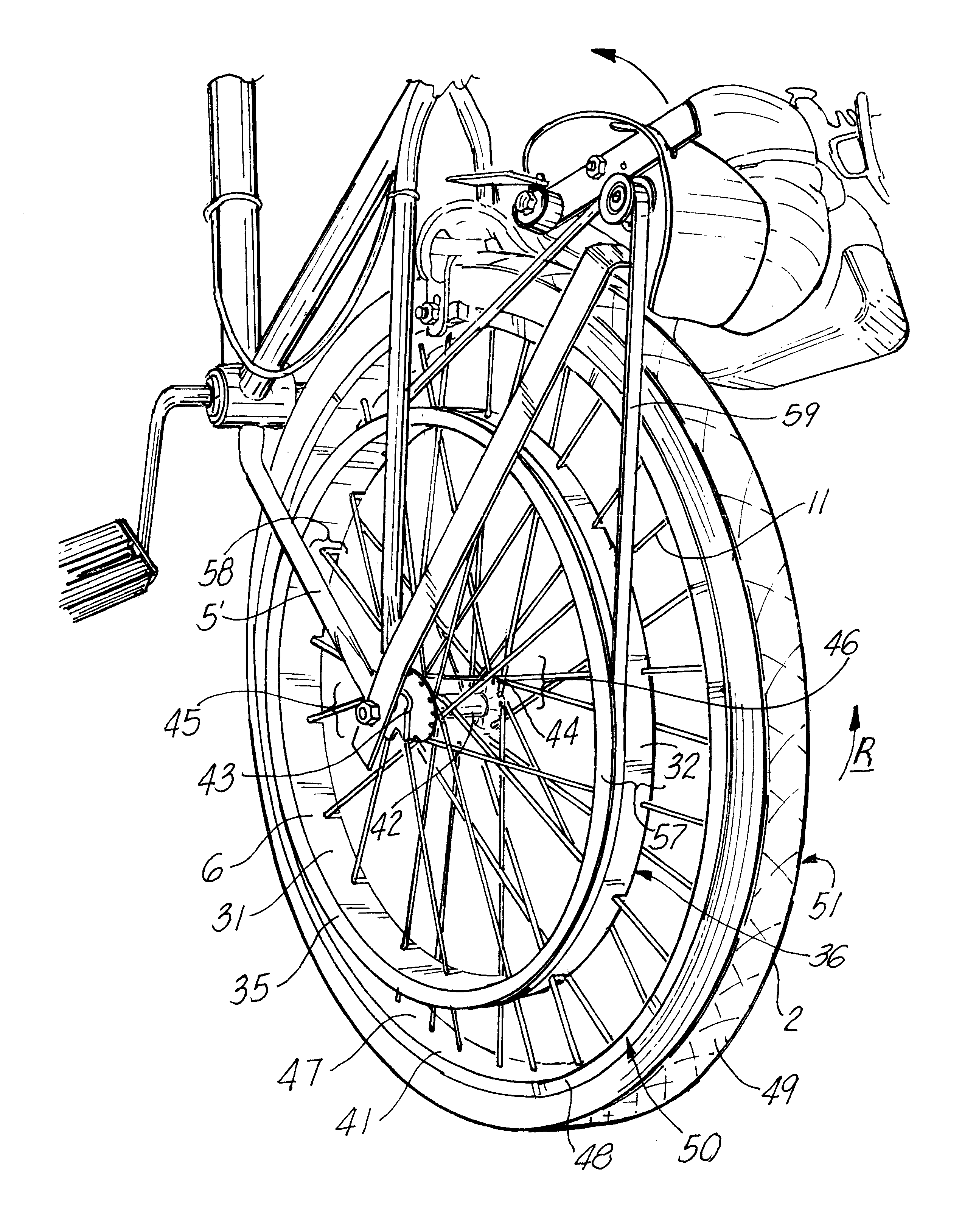
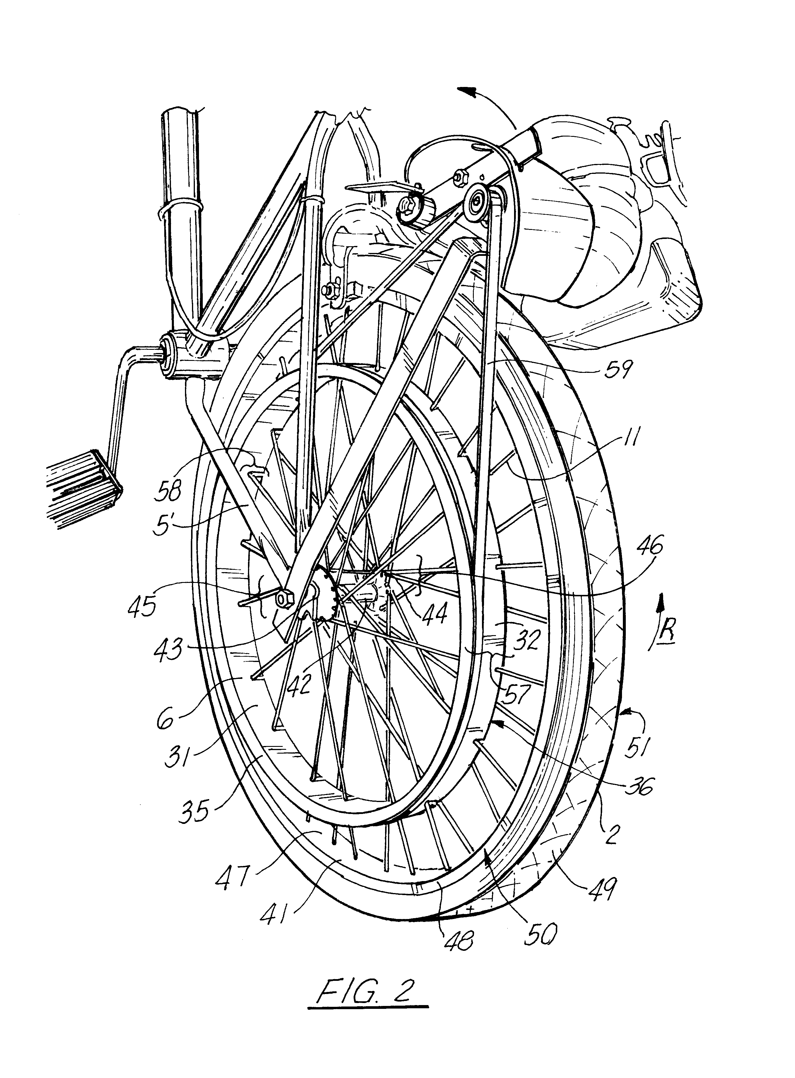
A motor unit 3, which includes a motor 27 (electric, internal combustion, etc) affixed to a motor mount 4 is mounted to the frame 5 of the vehicle, drives a drive hub 6, the drive hub being mounted to the spokes 8 of either the rear 2 or front 1 wheels via drive belt 59.

FIG. 1 illustrates the motor mount configuration as it would be implemented for driving the rear wheel of the cycle, but it is noted that the location of the motor can vary depending upon the type and application. Generally, the motor should be mounted in the vicinity of the wheel which is being driven, so if the front wheel of the cycle were to be driven utilizing the present invention, the motor should generally be mounted in the vicinity of the front whee...


PUM


Abstract

A drive hub configured to mount to the spokes of an off-the-shelf spoked wheel on a vehicle such as, for example, a bicycle, so as to allow said wheel to be driven by a motor mounted to the frame of the vehicle. The hub has an outer face including a channel or belt track for engaging a drive belt from the motor, and the inner side of the hub has formed therein spoke slots configured to accept and lock upon spokes situated on the front or rear wheel of the bicycle, and are situated such that the hub is self-centering upon installation, namely, when all of the slots are lined up to engage spokes on the bicycle, the hub is appropriately centered on said wheel. Each spoke slot is of a width so as to accept an individual spoke, with there being provided ridges, notches or the like in each slot for engaging and locking about the spoke to resist removal of the hub from the wheel, once mounted thereupon. The hub is driven by a small motor (electric or gasoline) mounted to the frame of the unit, via, for example, a friction belt drive system.

Description

The present invention relates to drive systems for bicycles or other operator powered, wheeled vehicles, and in particular to a system for converting a bicycle having at least one spoked wheel to enable motor propulsion or assist therefore.The preferred embodiment of the present invention teaches a spoke mounted, pulley / belt drive wherein there is provided a drive hub configured to quickly, easily, and safely mount to the spokes of an off-the-shelf spoked wheel on a vehicle such as, for example, a bicycle, so as to allow said wheel to be driven by a motor mounted to the frame of the bicycle.With the hub of the present invention, no special tools or measurements are required for mounting the unit. The hub has an outer face having formed therein a channel or belt track for engaging a drive belt from the motor; the inner side of the hub has formed therein spoke slots configured to accept and lock upon spokes situated on the front or rear wheel of the bicycle, which slots are situated s...

Claims


Application Information

Patent Timeline
Patent Type & Authority Patents(United States)
IPC IPC(8): B62M23/02B62M6/60
CPCB62M6/60
Inventor SIMONS, DENNIS R.
Owner SIMONS DENNIS R
Why Eureka
Try Eureka