Universal sliding rail assembly for rack mounting computers

a technology for computer racks and sliding rails, which is applied in the direction of rod connections, furniture parts, washing machines, etc., can solve the problems that the sliding rail assembly supplied by one manufacturer cannot be mounted in the rack supplied by another manufacturer, and many of the features and dimensions of commercially available rack structures are "non-standard", so as to achieve the effect of convenient removal and replacemen

Inactive Publication Date: 2003-06-17
HEWLETT PACKARD DEV CO LP
View PDF11 Cites 114 Cited by
  • Summary
  • Abstract
  • Description
  • Claims
  • Application Information

AI Technical Summary

Benefits of technology

A sliding rail assembly according to the invention is adjustable and adaptable so that it may be installed into a variety of different kinds of rack structures. In one aspect, an adjustable mounting flange is disposed on at least one of the two ends of the rail assembly. The adjustable mounting flange may be translated along the axis of the rail so that the length of the rail assembly adjusts to fit rack structures having various depths. In another aspect, two or more hooks are disposed on the rail assembly and extend orthogonally away from the rail so that the rail assembly may be hung on a rack structure while the assembly is being installed into the rack. The hooks are removable so that the rail assembly will fit into racks having narrow widths. In a third aspect, mounting adapters are provided for the mounting flanges so that the rail assembly may be mounted into racks whose corner posts have either round mounting holes or square mounting holes. In an embodiment, the mounting adapters take the form of a centering washer. In a fourth aspect, adjustable securing tabs are provided for mounting on at least one of the sides of a computer enclosure. The securing tabs engage the front corner posts of the rack structure, thereby preventing the rail and the enclosure from sliding out of the rack. The securing tabs may easily be removed and replaced so that they can be mounted at more than one location on the side of the computer enclosure. In this manner, the securing tabs are adjustable so that they accommodate rack structures having various depths.

Problems solved by technology

Consequently, many of the features and dimensions of commercially available rack structures are "non-standard."
For this reason, a sliding rail assembly supplied by one manufacturer typically cannot be mounted in a rack supplied by another manufacturer.

Method used


Image

  • Universal sliding rail assembly for rack mounting computers
  • Universal sliding rail assembly for rack mounting computers
  • Universal sliding rail assembly for rack mounting computers

Examples


Embodiment Construction

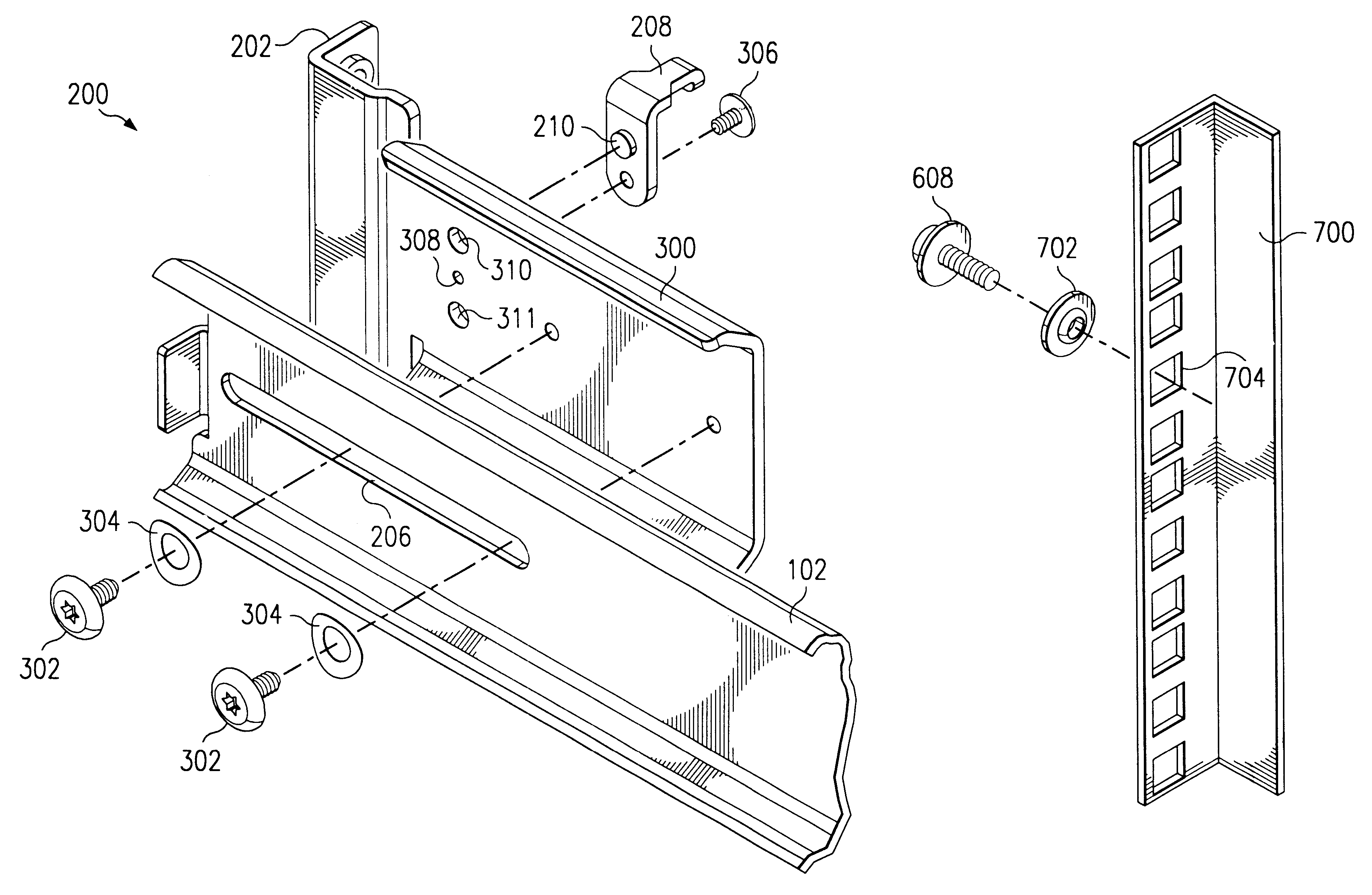
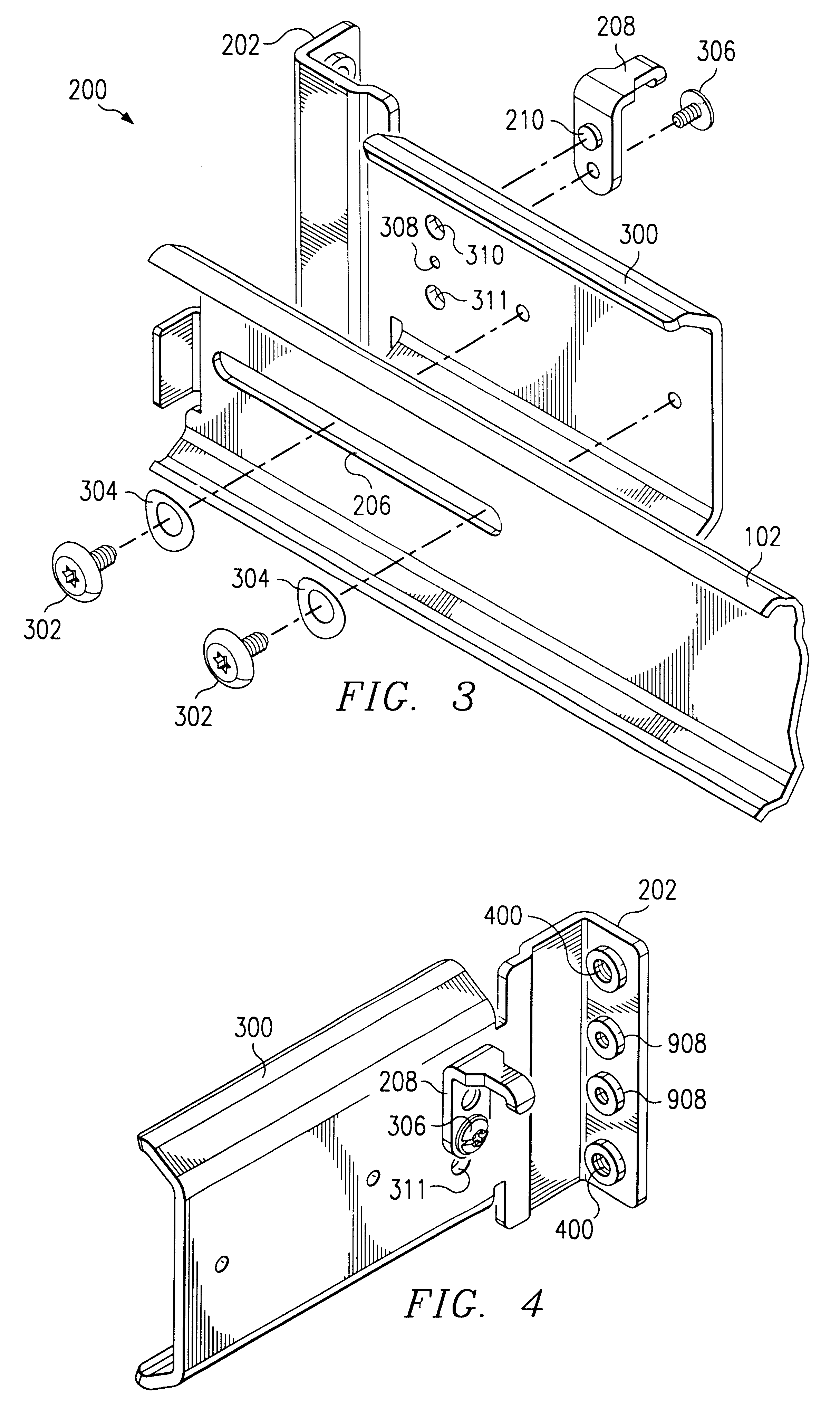
An adjustable slide rail assembly according to the invention may be employed in a variety of different rack mounting structures. Typically, such a rack structure will include four vertical corner posts, each of the posts having a vertical series of holes formed therein. The vertical series of holes is provided so that slide rail assemblies or trays may be mounted at a number of different heights in the rack, thereby forming numerous slots for receiving computers and supporting them in a stacked arrangement.

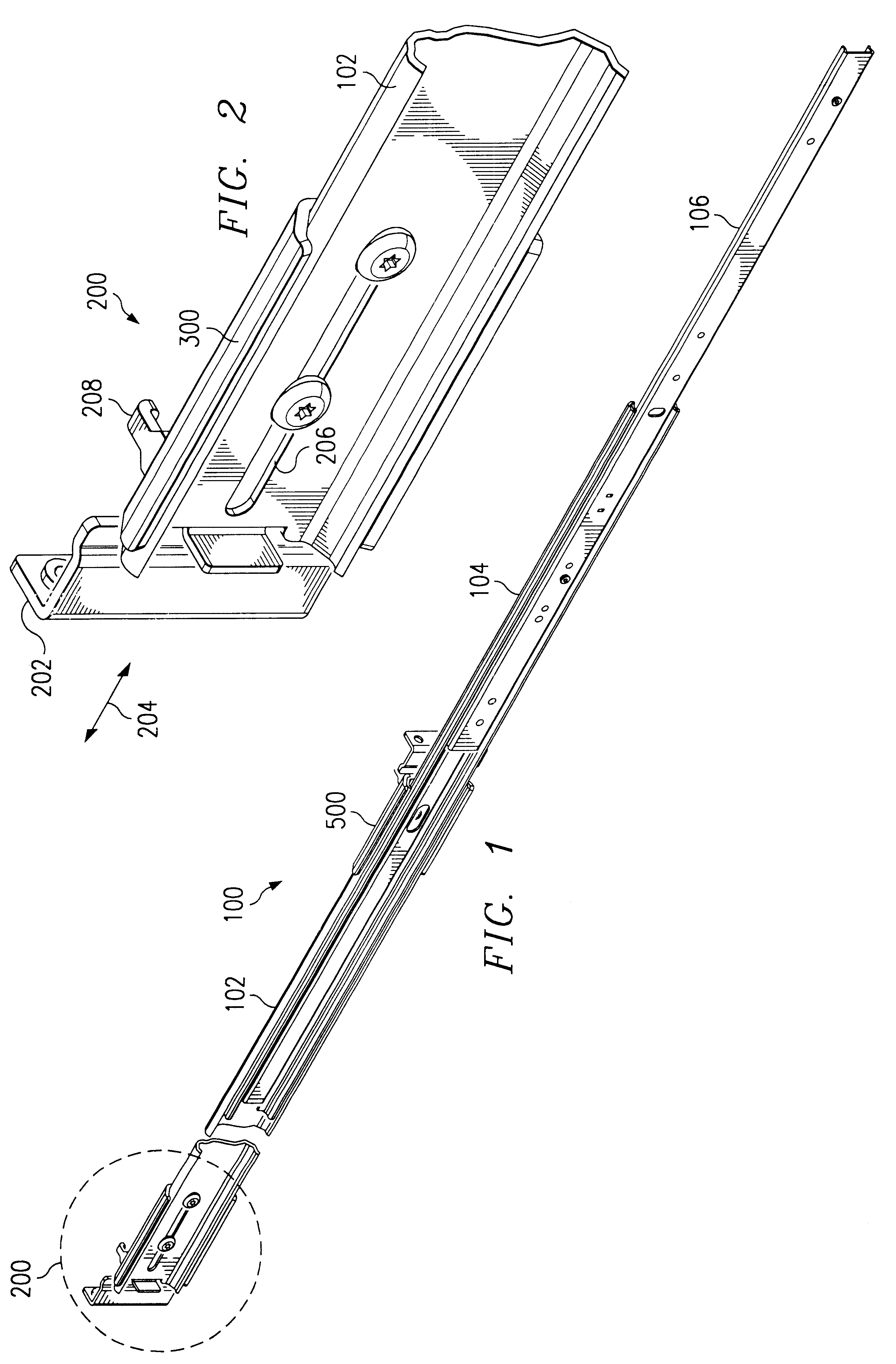
FIG. 1 illustrates an adjustable slide rail assembly 100 according to a preferred embodiment of the invention. Normally, a pair of rail assemblies 100 would be installed at the same height on the left and right sides of a rack to create one slot for receiving a computer. In the embodiment shown, slide rail assembly 100 includes a fixed rail 102 and two telescoping extending rails 104, 106. Other types of sliding rail designs may be used in alternative embodiments of the invention....


PUM


Abstract

A sliding rail assembly adjusts and adapts to fit various racks. An adjustable mounting flange on an end of the rail assembly translates along the axis of the rail so that the length of the rail assembly adjusts to fit racks having various depths. Hooks on the rail assembly may be used to hang the rail assembly on the rack while the rail assembly is being installed therein. The hooks are removable so that the rail assembly will fit racks having narrow widths. Mounting adapters enable the mounting flanges to mate with corner posts having round holes as well as those having square holes. Securing tabs engage front corner posts of the rack to prevent the rail and the computer enclosure from sliding out. To accommodate racks having various depths, the securing tabs may be mounted at more than one location on the side of the computer enclosure.

Description

FIELD OF THE INVENTIONThis invention relates to rack mounting techniques for computer enclosures.BACKGROUNDIn commercial settings, multiple computer enclosures are sometimes mounted in a vertical rack structure. This technique is referred to as "rack mounting," and is most frequently used with server-type computers that are accessed remotely via a network. Most rack structures include four vertical corner posts. Several pairs of horizontal sliding rail assemblies are attached to the corner posts to create slots or drawers in which the computer enclosures are received.Although most rack structures are built to comply with an Electronics Industry Association ("EIA") standard, the EIA standard specifies only a few of the features and dimensions that constitute a rack. Consequently, many of the features and dimensions of commercially available rack structures are "non-standard." That is, they differ substantially from one manufacturer to another. For this reason, a sliding rail assembly...

Claims


Application Information

Patent Timeline
Patent Type & Authority Patents(United States)
IPC IPC(8): A47B88/04A47B88/49
CPCA47B88/044A47B88/08Y10T403/3946Y10T403/3906A47B88/43A47B88/49F16B2200/506F16B9/058F16B9/052
Inventor MAYER, DAVID W.
Owner HEWLETT PACKARD DEV CO LP
Why Eureka
Try Eureka