Ground fault interruption receptacle

a ground fault and receptacle technology, applied in the direction of circuit-breaking switches, emergency protective arrangements for limiting excess voltage/current, coupling device connections, etc., can solve the problems of damage to users, damage to household electrical appliances,

Inactive Publication Date: 2003-06-17
HUANG HUADAO
View PDF2 Cites 123 Cited by
  • Summary
  • Abstract
  • Description
  • Claims
  • Application Information

AI Technical Summary

Benefits of technology

By using the above-described arrangement, the present invention provides more reliable protection to consumer and appliance in installing and using the ground fault interruption receptacle.

Problems solved by technology

(1) The electrical receptacle disclosed in U.S. Pat. No. 4,237,435 and in U.S. Pat. No. 4,247,840 will be cut-off immediately, when some component in operation is damaged. But its power input and output terminals might still be electrically connected to power source when the reset button of the receptacle is pushed down to reset the receptacle.
(2) In installing such an electrical receptacle, the installing worker can wrongfully connect the power source input terminal with the power source output terminal in the receptacle because the installing worker is unable to correctly distinguish between the power input terminal and the power output terminal, thereby connecting the power input terminal with receptacle's output terminal and connecting the power output terminal with receptacle's input terminal. Under such a condition, the receptacle with ground fault interruption function can still connect its input and output terminals with the power source. Under this condition, not only the electrical receptacle is unable to perform ground fault interruption function, it also misguides the users to continuously use this wrongfully connected receptacle. Thus it may cause harm to the users and damages and the household electrical appliances.

Method used


Image

  • Ground fault interruption receptacle
  • Ground fault interruption receptacle
  • Ground fault interruption receptacle

Examples


Embodiment Construction

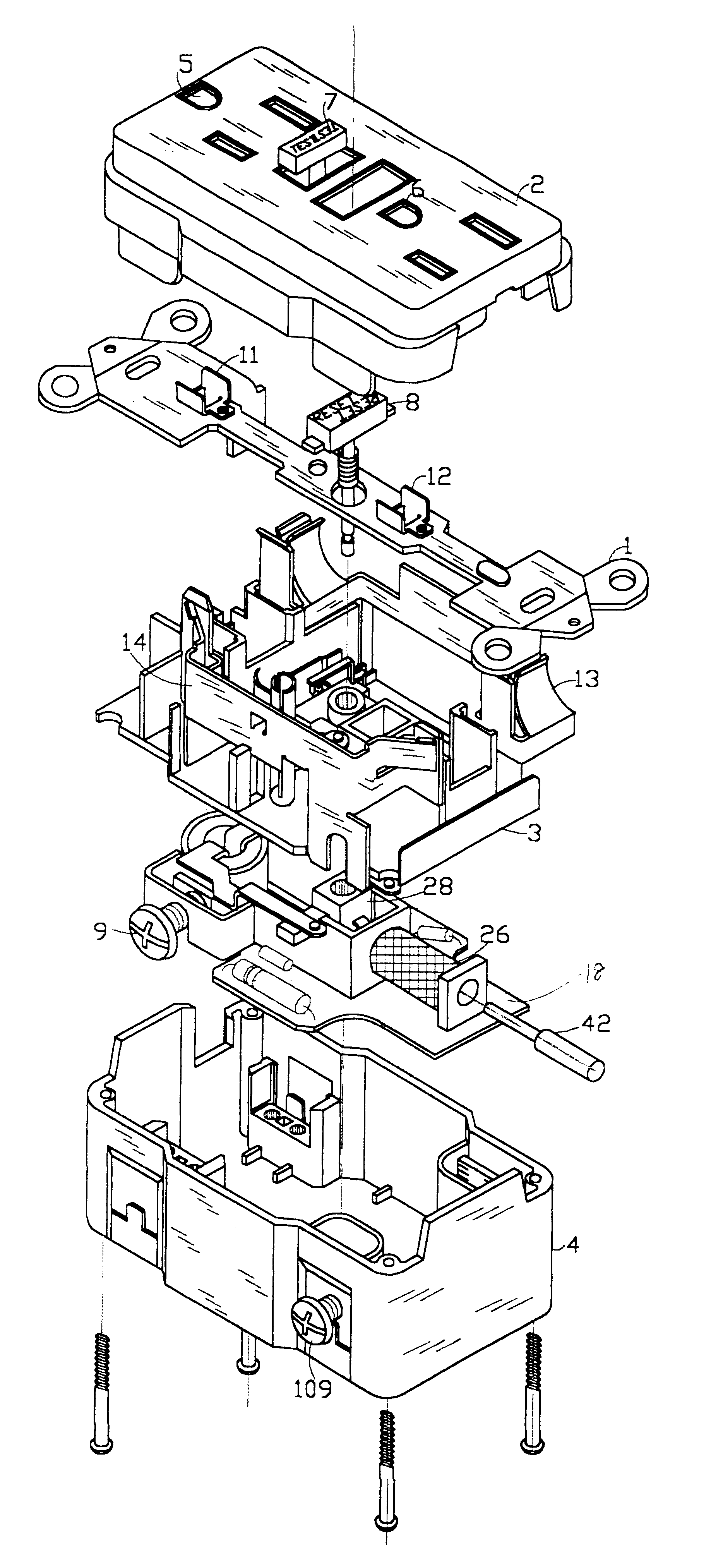
As shown in FIGS. 1 to 4 is an embodiment of the present invention. It mainly consists of an upper housing 2, a middle supporter 3 and a lower holder 4. In addition, between the upper housing 2 and the middle supporter 3 is mounted a metal mounting plate 1; and mounted between the middle supporter 3 and the bottom the lower holder 4 is a printed circuit board 18.

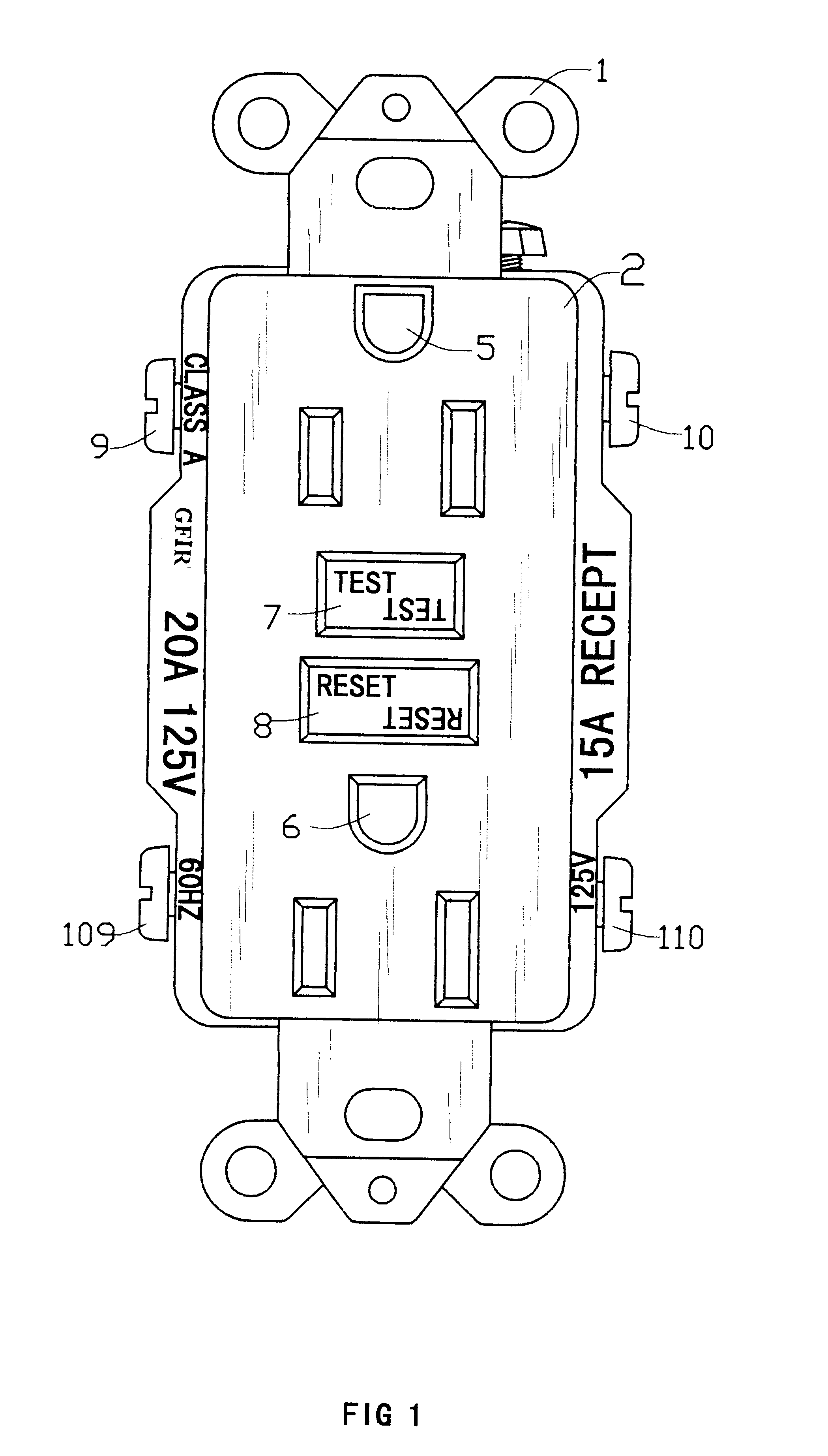
On the upper housing 2 are mounted two sets of female power-output socket 5, 6 used for receiving conventional male plug, a simulation test button 7 (TEST) and a reset button 8 (RESET).

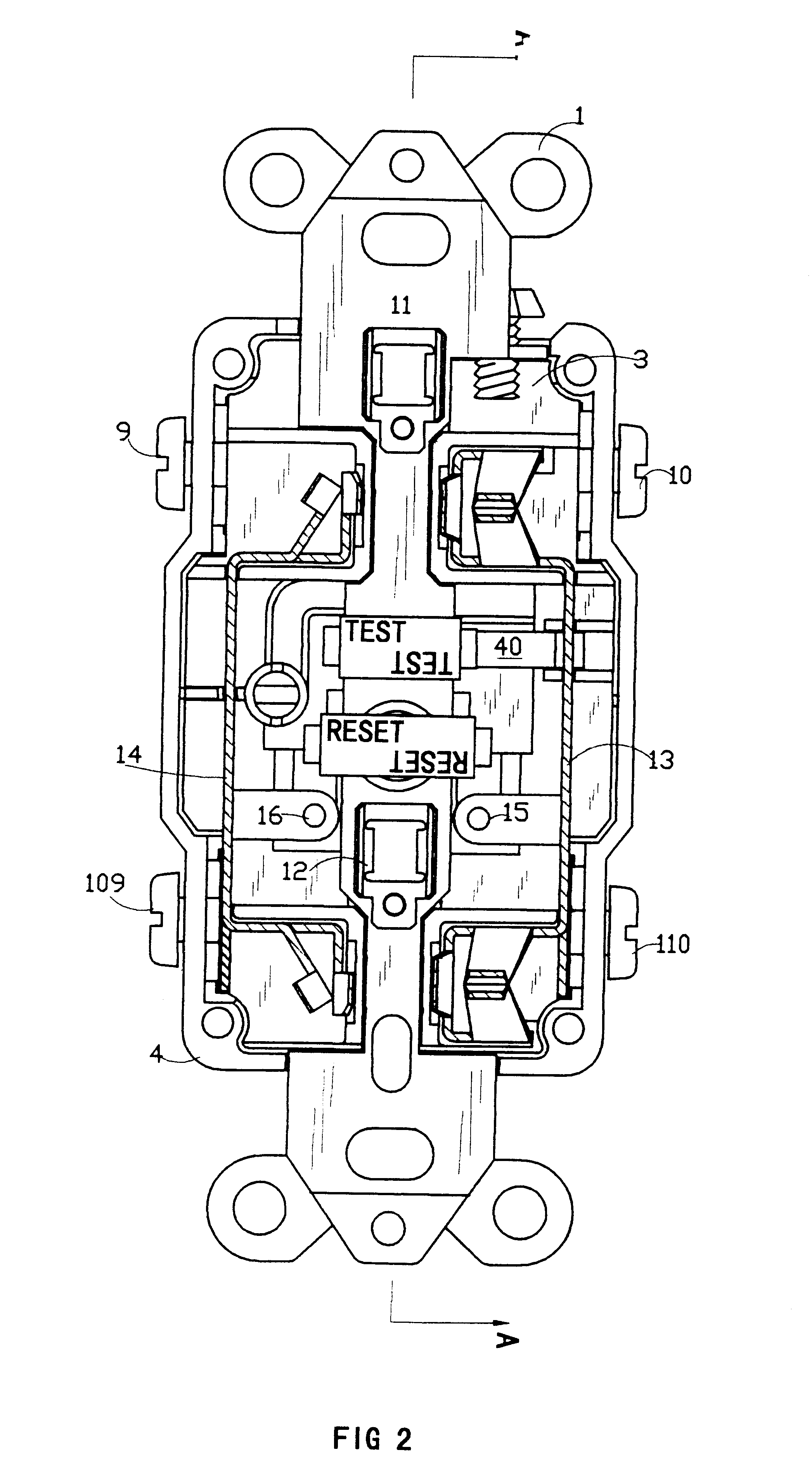
As shown in FIGS. 2 and 3, a metal mounting plate 1 is mounted on the upper housing 2. Through the holes on the upper housing 2, the grounding contacts 11 and 12 on the metal mounting plate 1 are connected with their respective lead-out grounding prongs of the power-out socket 5, 6. At the two sides of the supporter 3 are respectively disposed a pair of power-output metal conductors 13, 14. Thereon are respectively disposed a pair of power-out...


PUM


Abstract

A new and improved type of ground fault interruption receptacle is mainly consists of an upper housing, a middle supporter and a lower holder. Two sets of female power-output socket 5, 6, a simulation test button (i.e. test button for fault detecting) and a reset button are disposed on the upper housing. A metal mounting plate is disposed between the upper housing and the middle supporter. At the two sides of the middle supporter is disposed a pair of metal conductors. Between the middle supporter and the lower holder is disposed a printed circuit board, and thereon a differential transformer within which an iron core is inserted, a reset guide member and a flat spring type of resilient off locking switch are arranged. Using the differential transformer and the resilient off locking switch, the receptacle of the present invention may detect whether the fault current exists and whether the damage of a certain element or member for power transmission occurs. If so, the receptacle of the present invention can electrically disconnect the power-out connectors with the relevant power-input connectors so as to accomplish the ground fault interruption.

Description

FIELD OF THE PRESENT INVENTIONThe present invention generally relates to a receptacle with ground fault interruption function, and more specially, to a receptacle with ground fault interruption function which is suitable to be mounted into ordinary walls.BACKGROUND OF THE PRESENT INVENTIONWith people's living standard continuously rising and household electrical appliances being daily-increasingly popularized, the consumer demands that some electrical receptacles be pre-installed in walls when their houses are being built. However, at the present time, most of the electrical receptacles embedded in the walls are ordinary electrical receptacles and do not have ground fault interruption function. Although some of the electrical receptacles, for example, as those disclosed in U.S. Pat. No. 4,237,435 and in U.S. Pat. No. 4,247,840, have ground fault interruption function, they still have the following shortcomings:(1) The electrical receptacle disclosed in U.S. Pat. No. 4,237,435 and in...

Claims


Application Information

Patent Timeline
Patent Type & Authority Patents(United States)
IPC IPC(8): H01H83/00H01H83/04H01R13/70H01R13/713
CPCH01R13/7135H01H83/04
Inventor LI, CHENGLI
Owner HUANG HUADAO
Why Eureka
Try Eureka