Self-aligning shaft support

a shaft support and self-aligning technology, applied in the direction of sliding contact bearings, machines/engines, liquid fuel engines, etc., can solve the problems of difficult to provide an adequate seal, difficult to provide adequate seal, and insufficient arrangemen

Inactive Publication Date: 2003-07-01
HARBISON FISCHER
View PDF29 Cites 18 Cited by
  • Summary
  • Abstract
  • Description
  • Claims
  • Application Information

AI Technical Summary

Problems solved by technology

The problem of providing an adequate seal for members which are movable with respect to a base, such as rotating shafts or reciprocating pull rods, is well known.
This problem is made worse when the rotating or reciprocating member is caused to undergo relative lateral or angular displacement with respect to the housing in the region of the seal.
Generally, most parts of the support arrangement are machined and it is often difficult to provide an adequate seal.
This misalignment can occur where the drive means for the member is out of alignment with the central axis of the member or where due to a fault in the drive means the pump rod is caused to be flexed out of alignment during each stroke of the drive means.
In the past a variety of support arrangements have been proposed for accommodating for lateral or angular displacement of a movable member with respect to a housing, however these arrangements have not proved to be satisfactory where the movable member may be subjected to heavy tensional loads as in the case where a pump pull rod or high differential fluid pressure acts on the support assembly or seal.
It has been found, however, that while this arrangement has in many cases proved to be satisfactory where that assembly has been subjected to high load as a result of fluid pressure within the wellhead, high point loadings have been established between the bearing member and the bearing rings of the assembly which has limited the freedom of movement between the bearing member and the housing.
The abrasive nature of that fluid may cause speedy failure of the bearings and / or the associated seals.

Method used


Image

  • Self-aligning shaft support
  • Self-aligning shaft support

Examples


Embodiment Construction

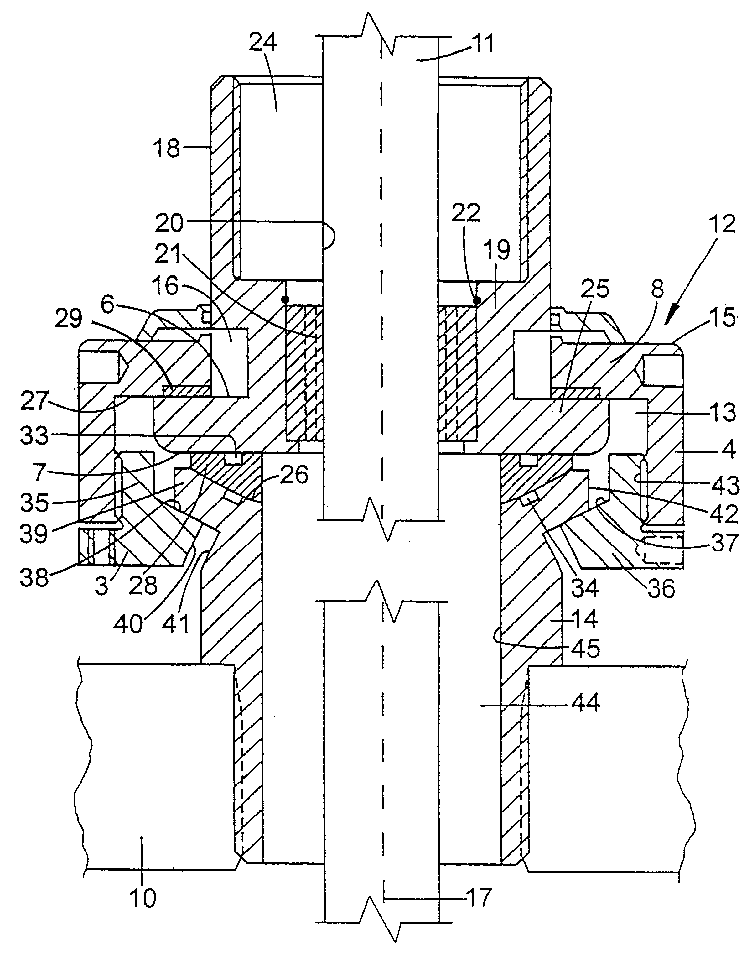
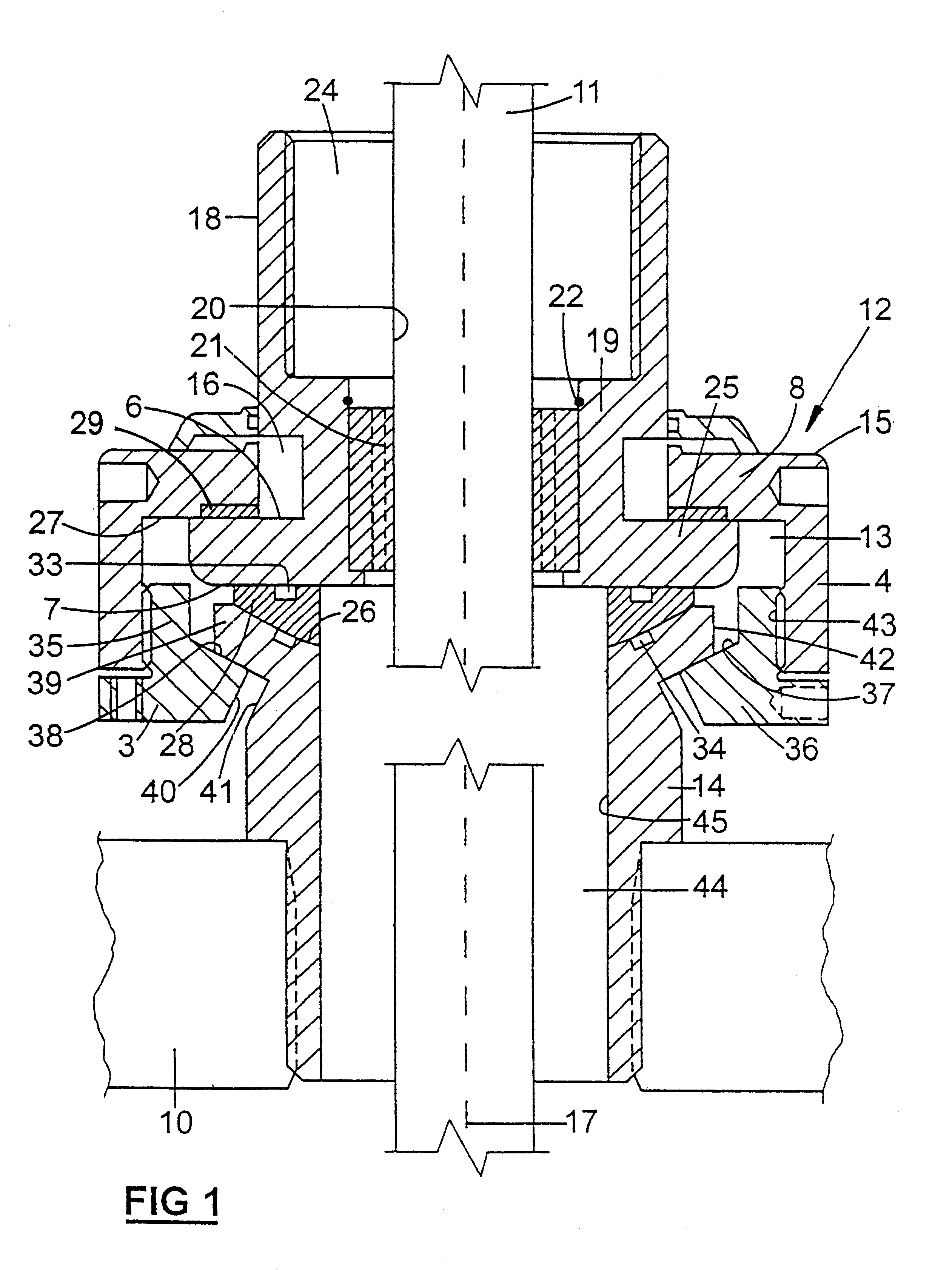
The accompanying drawing illustrates a support arrangement for supporting a pump pull rod 11 which is to be supported from a housing 10. The support arrangement has particular application where the pull rod 11 is likely, during its working life, to become misaligned with the central axis of the bore hole. In the past it has been found that the forces which are created by misalignment of the pull rod 11 can be particularly destructive to the sealing arrangement provided on housing 12.

The support arrangement includes a bearing housing 12 which defines a bearing chamber 13. The bearing housing 12 includes a substantially tubular base 14 and a cap member 15 which is movingly supported upon the base 14. Chamber 13 is defined between the outermost end of the base member 14 and the interior of the cap member 15. Base member 14 is adapted to be supported at its innermost end from the housing 10. Cap member 15 includes an upper end 8, a side wall 4 integral with end 8, and a lower portion 3....


PUM


Abstract

A guide to support a shaft such as a pump pull rod (11) which is capable of both rotary and reciprocal motion. The guide prevents any misalignment of rod (11) damaging a seal, e.g. a stuffing box, held in space (24). Guide element (18) has central portion (19) and annular flange (25). Element (18) can move laterally with respect to housing (12) and can also pivot, along with the cap (15) of the housing (12), with respect to the lower portion (14) thereof. The latter is achieved via movements of part-spherical bearing element (28) and similarly shaped faces (26, 37, 38) of housing 9120. Further seals (33, 34) prevents entry of pumped fluid into chamber (13).

Description

This invention relates to a support assembly to be used in association with a sealing arrangement to support a member which is movable with respect to a base element. In particular, this invention relates to a support assembly used to support the pull rod of a pump assembly adjacent the seal for the pull rod.REFERENCE TO RELATED PATENTThis invention is an improvement of the support assembly described in our earlier Australian patent 674209, the content of which is incorporated herein by reference.BACKGROUND TO THE INVENTIONThe problem of providing an adequate seal for members which are movable with respect to a base, such as rotating shafts or reciprocating pull rods, is well known. This problem is made worse when the rotating or reciprocating member is caused to undergo relative lateral or angular displacement with respect to the housing in the region of the seal.Generally, most parts of the support arrangement are machined and it is often difficult to provide an adequate seal. Fur...

Claims


Application Information

Patent Timeline
Patent Type & Authority Patents(United States)
IPC IPC(8): F16C23/00F04B53/14F04B53/00F16C23/04F16J15/18
CPCF04B53/144F16C23/04F16J15/187
Inventor RIMMER, IAN
Owner HARBISON FISCHER
Why Eureka
Try Eureka