
Projector device

a projector and projection device technology, applied in the field of projector devices, can solve problems such as the disadvantage of being increased in thickness

Inactive Publication Date: 2003-07-08
FUJI PHOTO OPTICAL CO LTD
View PDF4 Cites 32 Cited by
  • Summary
  • Abstract
  • Description
  • Claims
  • Application Information

AI Technical Summary

Problems solved by technology

However, this projector device according to the prior art, since the illuminating light should be brought to incidence on the TIR prism 8 in a direction at 45.degree. to the long side of the DMD 1 as shown in FIG. 8 and FIG. 9, involves the disadvantage of being increased in thickness.

Method used


Image

  • Projector device
  • Projector device
  • Projector device

Examples


Embodiment Construction

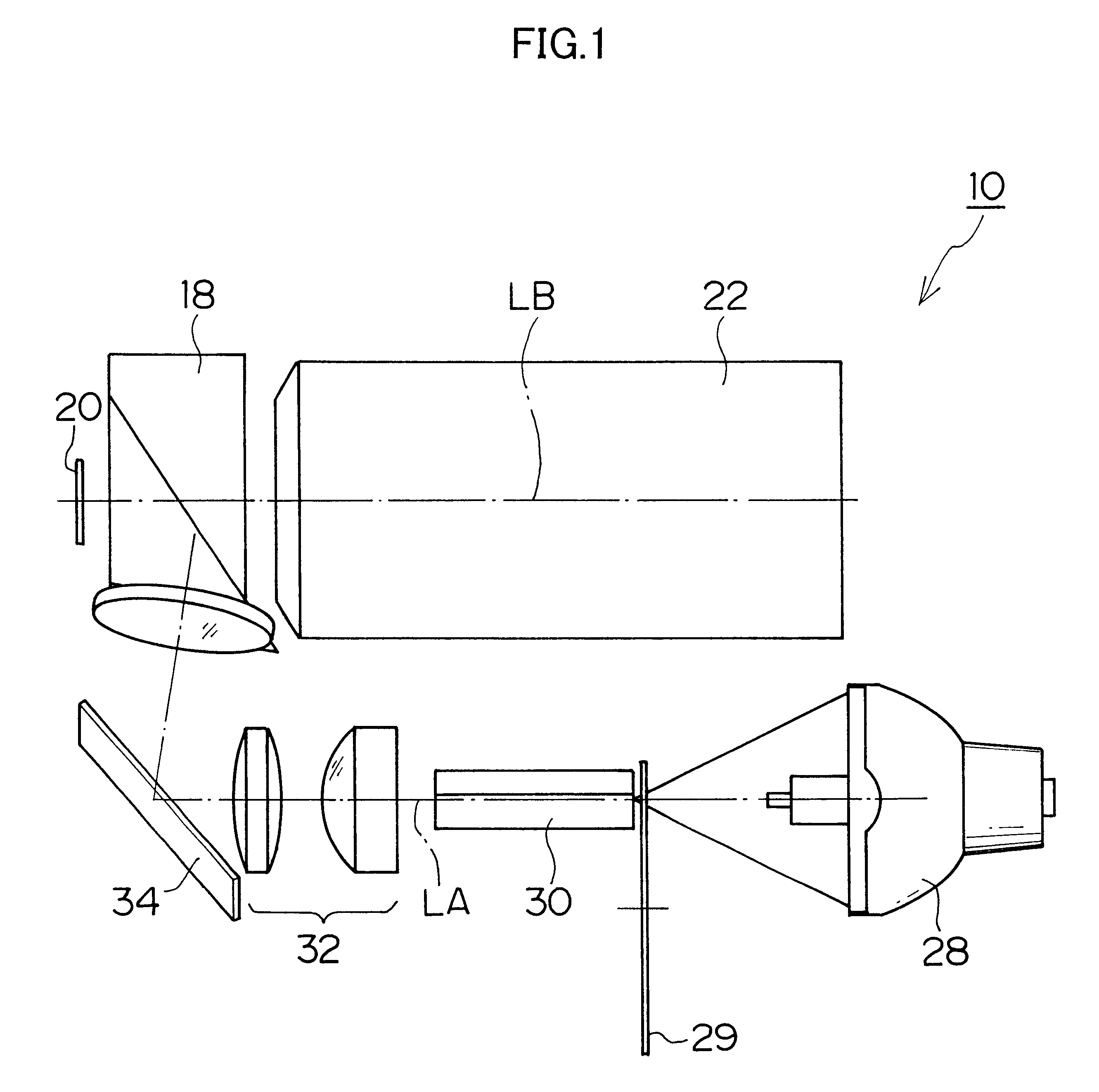
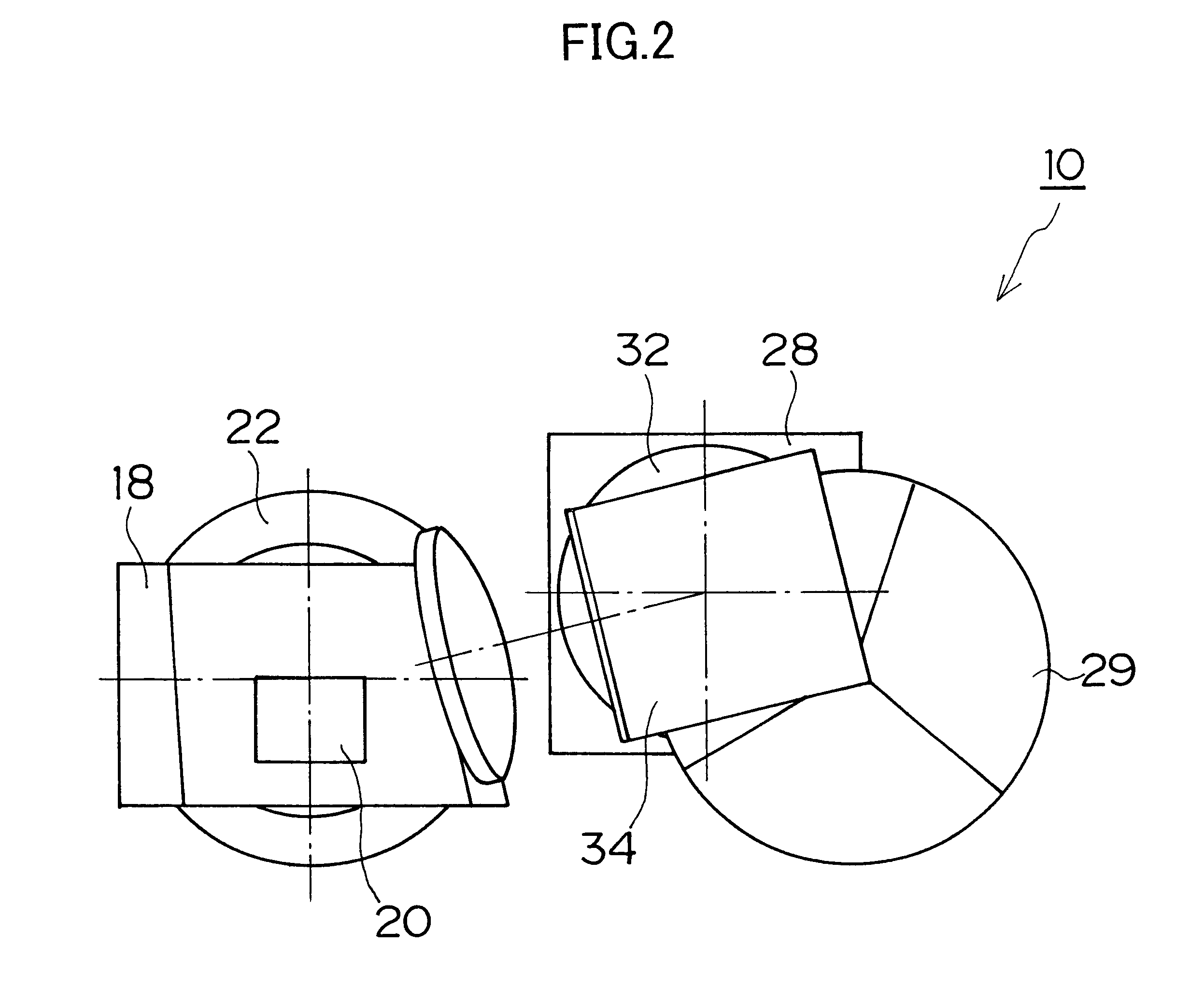
Next will be described an example of TIR prism to be applied to a projector device pertaining to the present invention.

The example explained here is a TIR prism applicable to a projector device using a DMD whose micromirrors are inclined at .+-.12.degree..

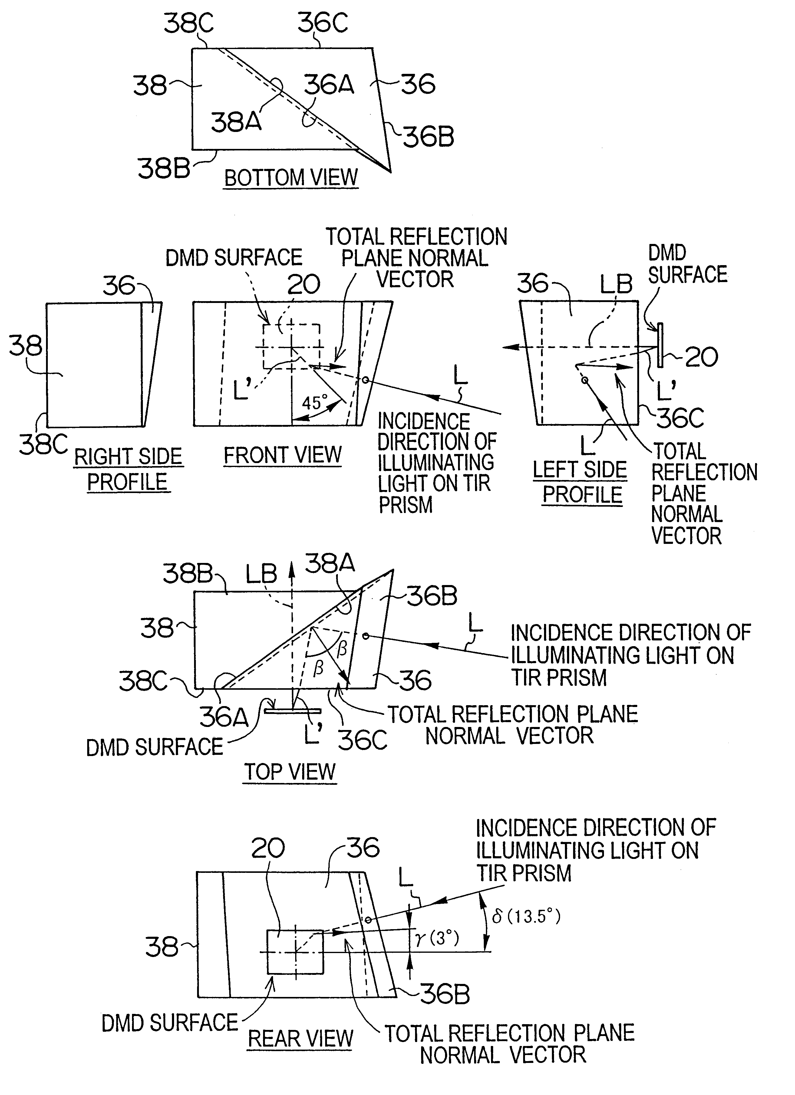
As described above, in a DMD whose micromirrors are inclined at .+-.12.degree., it is necessary for the illuminating light to irradiate the surface of the DMD 20 at an incidence angle of 24.degree. to the surface of the DMD 20 in a direction forming an angle of 45.degree. to the long or short side of the DMD 20.

As illustrated in FIG. 3 and FIG. 4, the illuminating light is brought to incidence vertically on the incidence plane 36B of the first prism 36, totally reflected by the total reflection plane 36A, and guided to the DMD 20. Then, the projecting light reflected by the DMD 20 is totally transmitted by the total reflection plane 36A of the first prism 36 and the second prism 38 and guided to the projecting optical system 22.

The...


PUM


Abstract

The projector device can be reduced in thickness by using a total internal reflection (TIR) prism wherein the angle formed between a line of projection of the normal vector of the total reflection plane on the surface of a digital micromirror device (DMD) and the long or short side of the DMD is set to be smaller than 45°. The TIR prism has a total reflection plane for totally reflecting illuminating light brought to incidence by an illuminating optical system to guide it to the DMD and totally transmit light optically modulated by the DMD to guide it to a projecting optical system, and this total reflection plane is so arranged relative to the DMD that the angle formed between a line of projection of its normal vector on the surface of the DMD and the long side of the DMD form an angle smaller than 45°. An incidence plane on which the illuminating light is brought to incidence by the illuminating optical system is so formed that the illuminating light brought to incidence vertically on its incidence plane, when totally reflected by the total reflection plane and emitted from an emission plane toward the DMD, be emitted at an incidence angle of 24° to the surface of the DMD in a direction at an angle of 45° to the long side of the DMD.

Description

1. Field of the InventionThe present invention relates to a projector device, and more particularly to a projector device for projecting images on a screen by using a digital micromirror device (DMD).2. Description of the Related ArtA DMD is configured of a large number of micromirrors arranged in a matrix, in which each micromirror constitutes one pixel of a displayed image. Each micromirror takes one of two inclined states, an ON state and an OFF state. In the ON state, illuminating light is reflected into a projecting optical system, while in the OFF state it is projected away from the projecting optical system. Therefore, in a projector device using a DMD, the projecting optical system projects only the light reflected by micromirrors in the ON state, resulting in the formation of a displayed image composed of a pattern of different levels of brightness on the screen.FIG. 5 shows a plan of a micromirror drive structure in a DMD, and FIG. 6 shows the 6--6 section in FIG. 5. The d...

Claims


Application Information

Patent Timeline
Patent Type & Authority Patents(United States)
IPC IPC(8): H04N5/74H04N9/31G02B27/18G02B5/04G03B21/00G03B21/14
CPCH04N5/7458H04N9/3141H04N9/3102
Inventor SHIMIZU, HITOSHI
Owner FUJI PHOTO OPTICAL CO LTD
Learn More