System for the automatic adaptation of projector images and a method for the implementation thereof

a projector image and automatic adaptation technology, applied in the field of computerized projector systems, can solve problems such as complicated and difficult control

Inactive Publication Date: 2003-07-22
IBM CORP
View PDF14 Cites 70 Cited by
  • Summary
  • Abstract
  • Description
  • Claims
  • Application Information

AI Technical Summary

Problems solved by technology

Other methods and systems incorporating reflective light valve projectors utilize three light valves in which a considerable number of components consisting of an illumination module with various mirrors operate

Method used


Image

  • System for the automatic adaptation of projector images and a method for the implementation thereof
  • System for the automatic adaptation of projector images and a method for the implementation thereof
  • System for the automatic adaptation of projector images and a method for the implementation thereof

Examples


Embodiment Construction

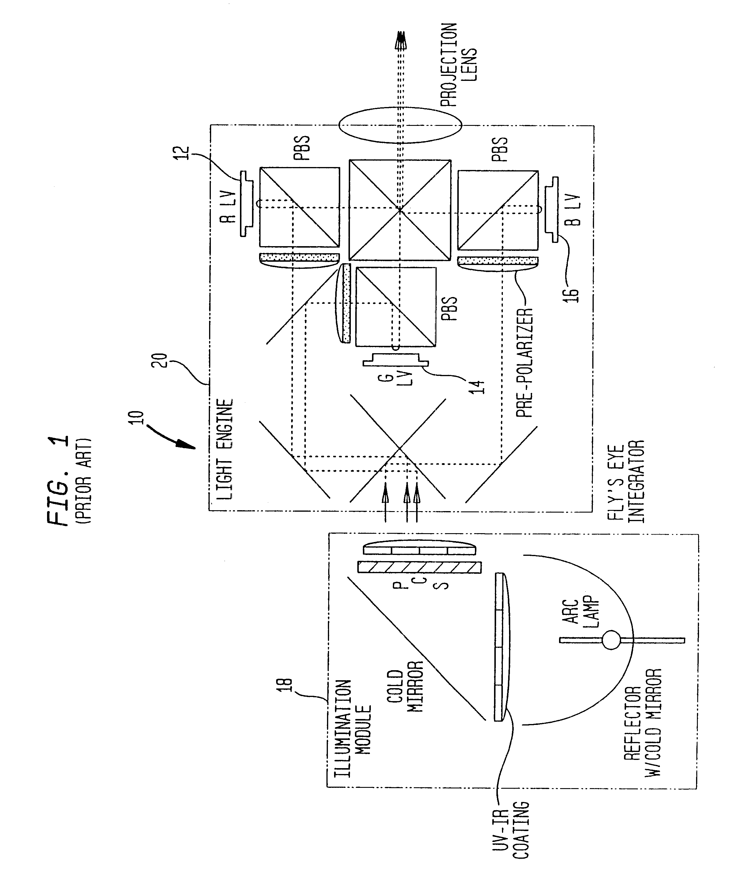
Referring now in detail to the drawings, and particularly the prior art system for projecting images onto a screen as shown in FIG. 1, of the type set forth in the above-mentioned U.S. patents, there is shown a reflective light valve projector 10, such as a digital projector, utilizing three light valves 12, 14, 16, wherein an illumination module 18 containing various optical components operates in conjunction with a light engine 20 containing the light valves, utilizing a complex system of lenses and projection optics in order to provide images onto a screen. This is a relatively complex system requiring a considerable amount of components and does not always provide for the appropriate automatic corrective images, particularly when the screen is irregular in its configuration and curvature, is angularly oriented relative to the projector 10, or is subjected to sunlight or various light spots.

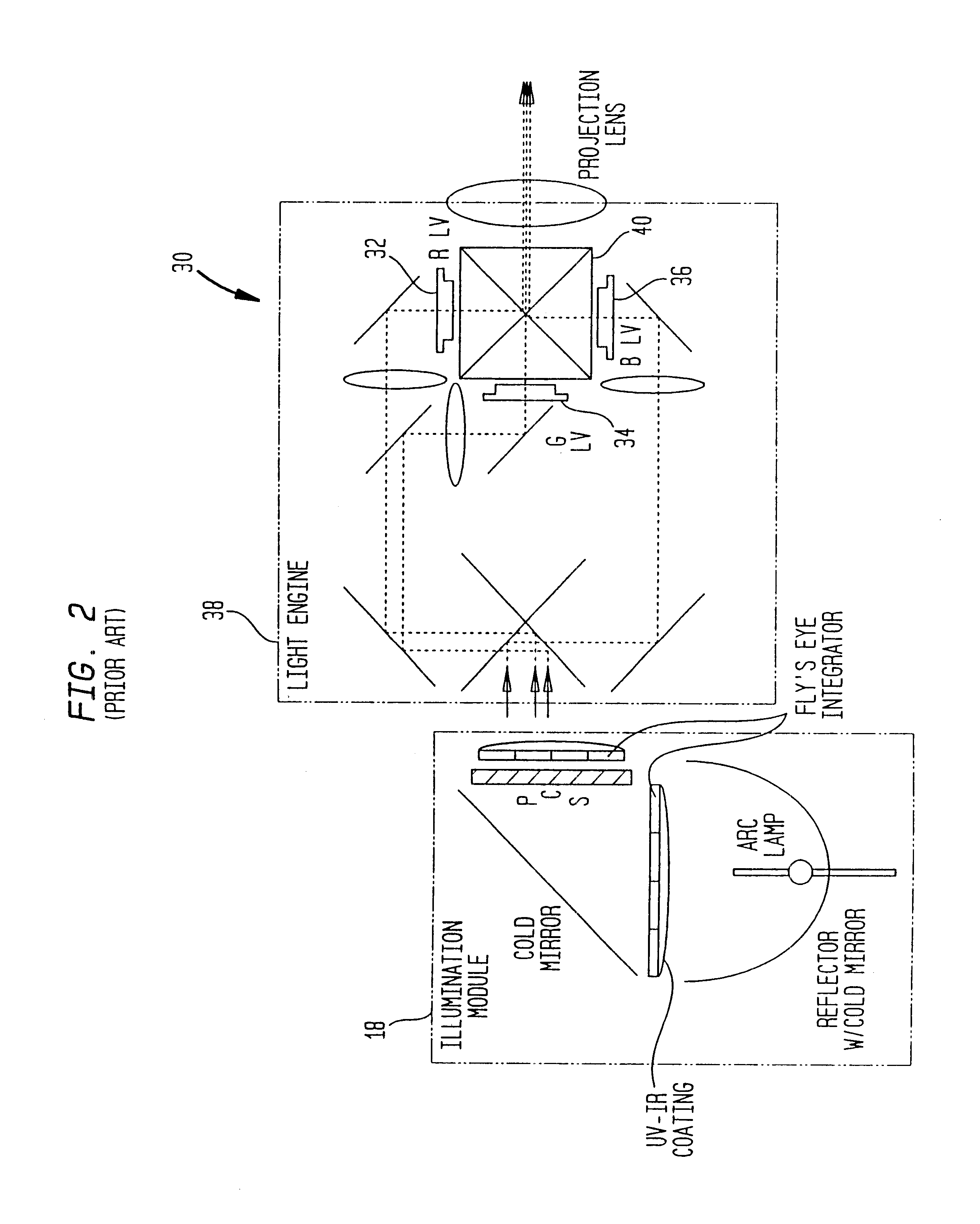
Similarly, as illustrated in FIG. 2 of the drawings, there is shown a further prior art tr...


PUM


Abstract

A computerized projector system which automatically adapts projected images emanating from projectors to fit the size and conditions of screens on which the images are displayed. Moreover, disclosed is a novel method of utilizing a computerized projector system which automatically adapts projected images to a shape and condition in correlation with the size and configuration of the screens onto which the images are projected.

Description

1. Field of the InventionThe present invention relates to a computerized projector system which automatically adapts projected images emanating from projectors to fit the size and conditions of screens on which the images are displayed. Moreover, the invention is directed to a novel method of utilizing a computerized projector system which automatically adapts projected images to a shape and condition in correlation with the size and configuration of the screens onto which the images are projected.In projecting images onto a screen, the latter of which may be a standard projector screen, a wall surface, a paper listing, a ceiling, a floor or any covering surface adapted to have images projected thereon and displayed, upon occasion the projector may be viewing or directing images towards the screen from an angle such that an upper part of the image may be wider than the lower part of the image, thereby providing a distorted image. This is frequently an occurrence when the screen or d...

Claims


Application Information

Patent Timeline
IPC IPC(8): G09G3/00H04N9/31H04N5/74H04N17/00
CPCH04N5/74H04N9/3182H04N9/3185H04N9/3194H04N9/3197G09G3/002G09G2320/029G09G2320/0626G09G2320/0666G09G2340/04G09G2360/144
Inventor DOANY, FUAD ELIASKANEVSKY, DIMITRIZLATSIN, ALEXANDER
Owner IBM CORP
Why Eureka
Try Eureka