Flooring panel or wall panel

a technology of floor or wall panel and wall panel, which is applied in the direction of floor, building components, covering/lining, etc., can solve the problems of difficulty in the movement of the two flooring panels joined together relative to each other, tongue slips out of place from the groove,

Inactive Publication Date: 2003-08-05
PERSTORP AB +1
View PDF58 Cites 337 Cited by
  • Summary
  • Abstract
  • Description
  • Claims
  • Application Information

AI Technical Summary

Benefits of technology

In any case, however, both the upper and lower side of the tongue is provided with a locking means for a flooring panel or wall panel in accordance with the invention, locking means being provided correspondingly on the surface area defining the tongue both upper and lower. In accordance with the invention an additional surface portion formed as a step or bevel is provided on the surface area of the upper and / or lower cheek of the groove facing the groove. It is this aspect that facilitates producing the joint since when inserting the tongue, shifting it in the insertion direction requires little exertion force or may even require none at all. Insertion direction in this context is understood to be the direction in which the tongue is inserted into the groove to join two adjoining panels to each other. The insertion direction thus extends perpendicular to the edge as observed of the panel.
One particularly advantageous feature applicable to the flooring panel or wall panel in accordance with the invention consists of the lower cheek of the groove being thinner than its upper cheek so that the lower cheek is more pliant than the upper cheek and is deformed to a greater extent than the upper cheek of the groove when joining two adjoining panels. Preferably the upper cheek of the groove should not deform at all to eliminate the risk of steps forming when joining the panels together. Instead only the lower cheek of the groove should slightly deform on joining before snapping back into place for a secure lock. The comparitively thick and thus comparatively stiff upper cheek of the groove or lip also contributes towards maintaining the floor surface area flat once the panels have been joined and when accessed.

Problems solved by technology

As it reads from this disclosure, however, a certain clearance needs to remain, thus resulting in this building element not at all being suitable for floor or wall finishes which for a pleasing appearance need to be joined free of clearance and accordingly with no gaps.
Due to the angled surfaces of the tongue and of the surfaces of the groove shaped angled thereto it may often occur that the tongue slips out of place from the groove because of insufficient force being exterted in the insertion direction.
The reason for this could be that due to the stagger, any movement of the two flooring panels joined together relative to each other is made difficult.

Method used


Image

  • Flooring panel or wall panel
  • Flooring panel or wall panel
  • Flooring panel or wall panel

Examples


Embodiment Construction

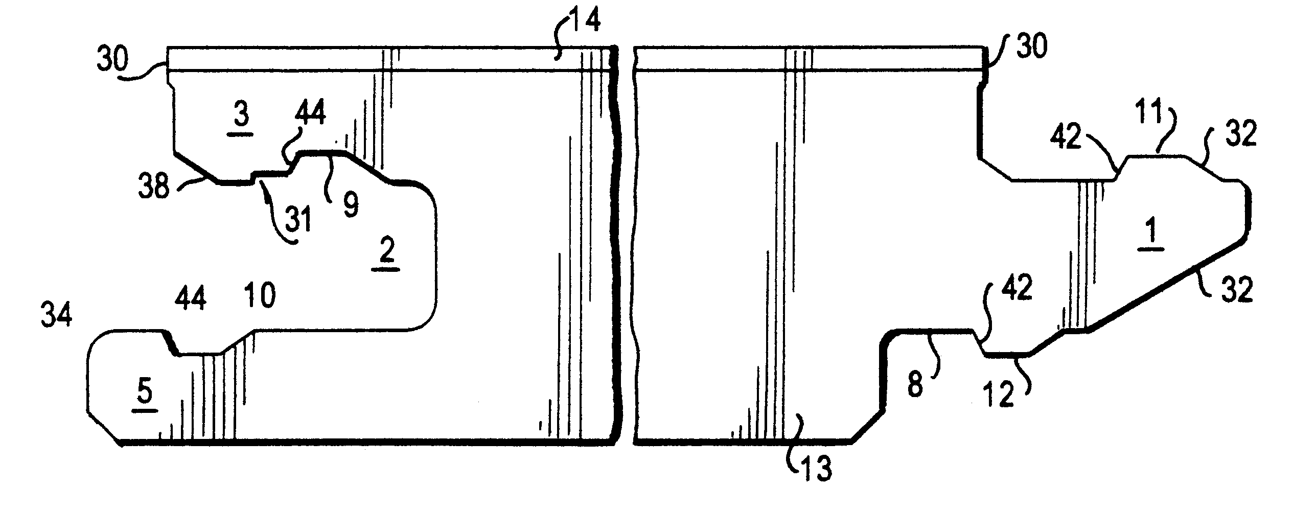
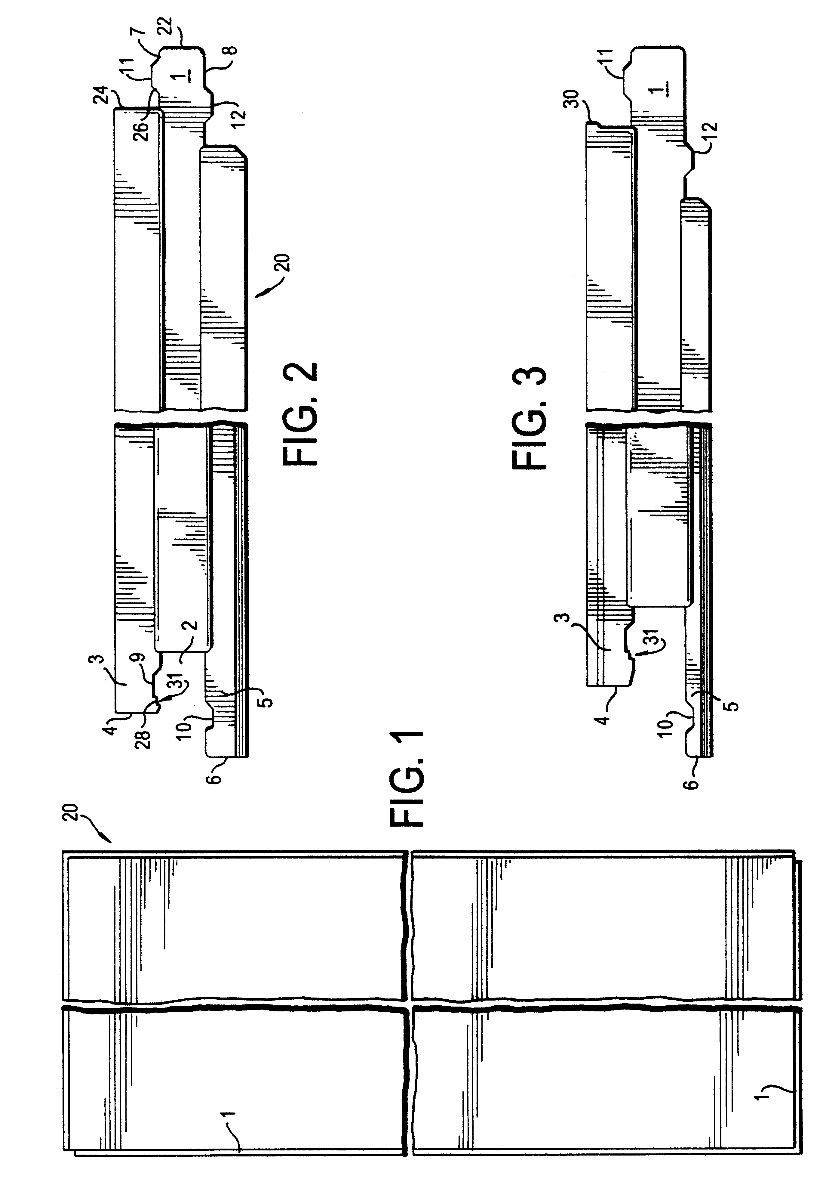
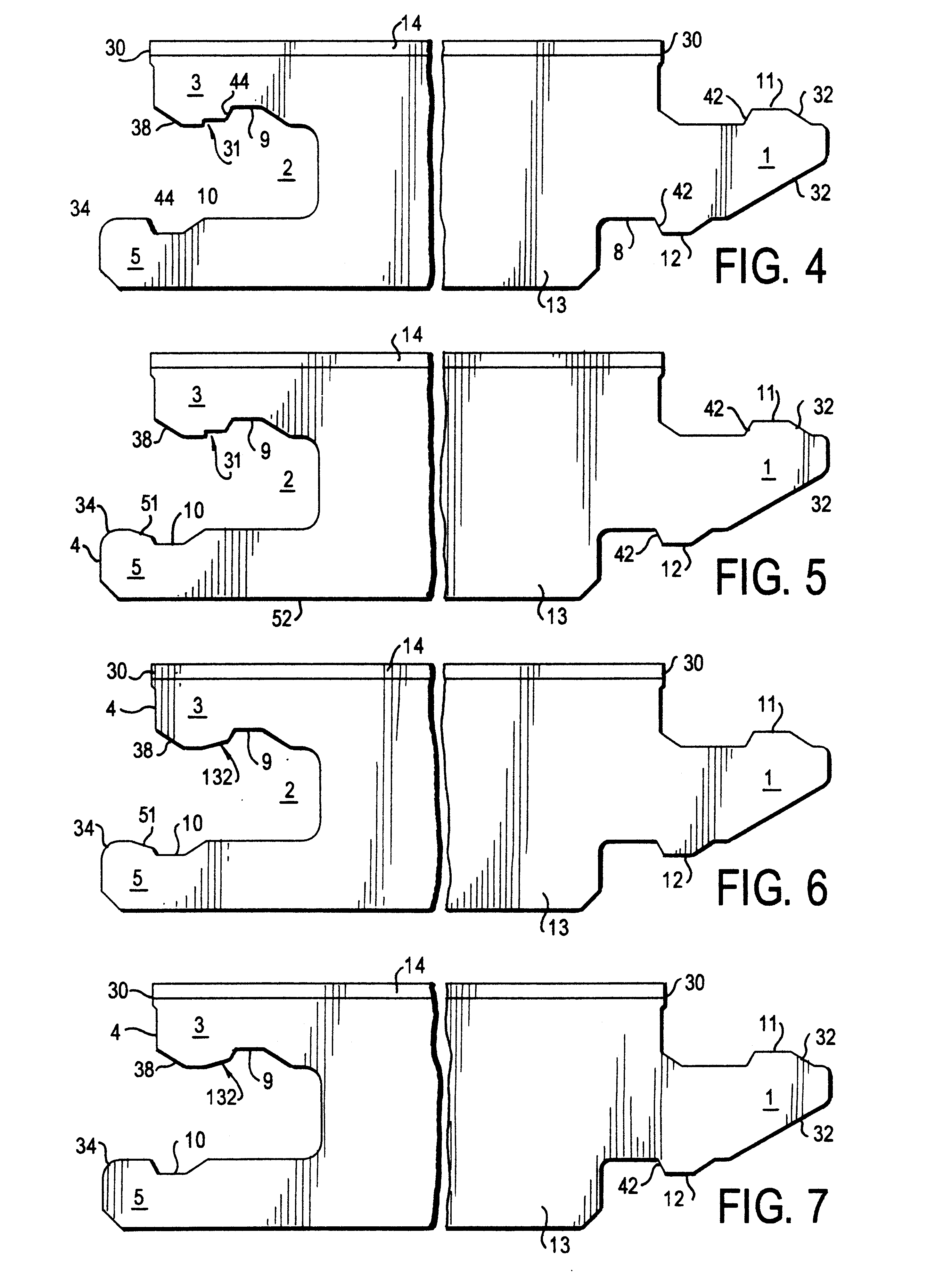
Referring now to FIG. 1 there is illustrated a plan view of the flooring panel or wall panel in accordance with the invention in which it is to be noted that to simplify the illustration only a few corner portions of the panel 20 are shown and that the panel may be dimensioned optionally between these corner portions as shown, it more particularly being shaped either square or rectangular. Configured at the (longer) longitudinal edges of the embodiment of the panel 20 as shown is on the one side (on the left in FIG. 1) a tongue 1 and on the opposite side a groove. Likewise on the lower short side as shown in FIG. 1 a tongue 1 is configured with a groove provided on the opposite short side. It is obvious that due to this configuration panels of the same kind can be joined together to form a complete floor finish. It is to be noted that the tongue 1 and the locking means as to be later described are configured continuous and full-length in each of the preferred embodiments, although i...


PUM

PropertyMeasurementUnit
lengthaaaaaaaaaa
surface areaaaaaaaaaaa
forceaaaaaaaaaa

Abstract

A flooring panel or wall panel (20) is provided with a tongue (1) and a groove (2) each comprising cooperating locking means in the form of ribs (11, 12) and grooves (9, 10). The locking means of the upper side and lower side of the tongue (1) and groove (2) respectively are arranged staggered in an insertion direction in which the two panels to be joined to each other are joined to configure a firm joint between two adjoining panels at which an additional surface portion (31; 32; 51) step (31) is provided at the surface area of the upper cheek (3) facing the groove (2) and / or of the lower cheek (5) of the groove which is formed as a step (31) or bevel (32: 51).

Description

The invention relates to a flooring panel or wall panel as set forth in the preamble of claim 1.In recent years laminated floor finishes have become increasingly popular in replacing parquet floors and wall-to-wall carpeting. In the production of laminated floor finishes a decorative thermosetting laminate is first produced. This laminate usually consists of a base layer of paper sheets, impregnated with phenol-formaldehyde resin, and a decorative surface layer comprising a decor paper sheet impregnated with melamine formaldehyde resin. The laminate is produced by compressing the various layers at a high pressure and an elevated temperature. The laminate thus obtained may then be bonded to a backing, for example of particle board, or used as such without a backing, it then be termed a compact laminate. The resulting laminated panel of large surface area is then sawn up into a number of floor boards each provided with tongues and grooves at their long and short sides. These floor boa...

Claims


Application Information

Patent Timeline
Patent Type & Authority Patents(United States)
IPC IPC(8): E04F15/10E04F15/02E04F13/16
CPCE04F13/16E04F15/02E04F15/10E04F2201/0115E04F2201/023
Inventor OLOFSSON, OLA
Owner PERSTORP AB
Why Eureka
Try Eureka