

Support pad for a deep hole drill
- Summary
- Abstract
- Description
- Claims
- Application Information
AI Technical Summary
Problems solved by technology
Method used
Image

Examples
Embodiment Construction
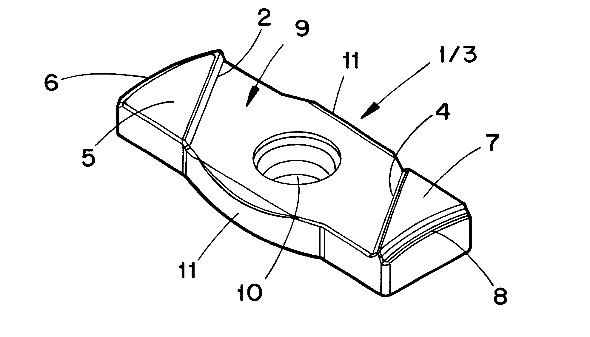
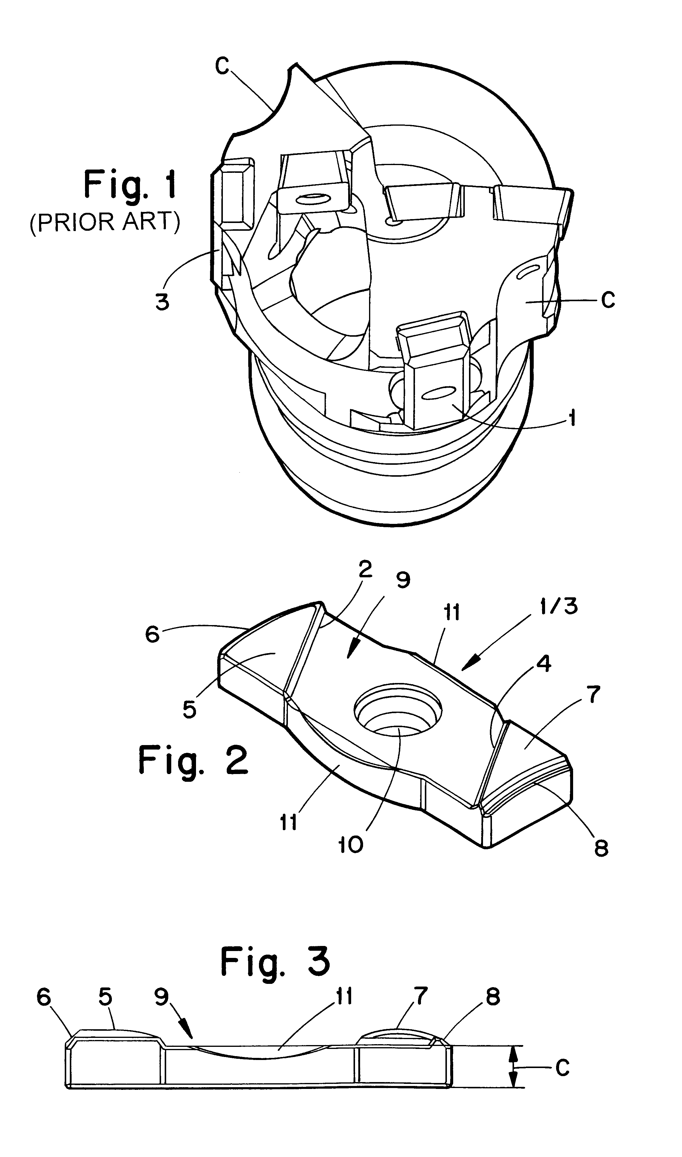
The cutter head of a deep hole drill illustrated in FIG. 1 is equipped with a support pad 1 as well as a guide bar 3. The support pad 1 and the guide bar 3 are received in seats and anchored in said seats by means of [the principle for indexable inserts. i.e. by means of] a screw (not visible in FIG. 1) which extends through a hole in the support pad 1 / guide bar 3 and anchors this in the appurtenant seat thanks to the screw extending into a threaded hole in the cutter head.
Furthermore, the cutter head is, in the usual way, equipped with a cutting insert and provided with openings and an inner channel for removal of chips, which are generated at drilling. However, these details are not described further in the present patent application since they do not constitute any part of the invention in question.
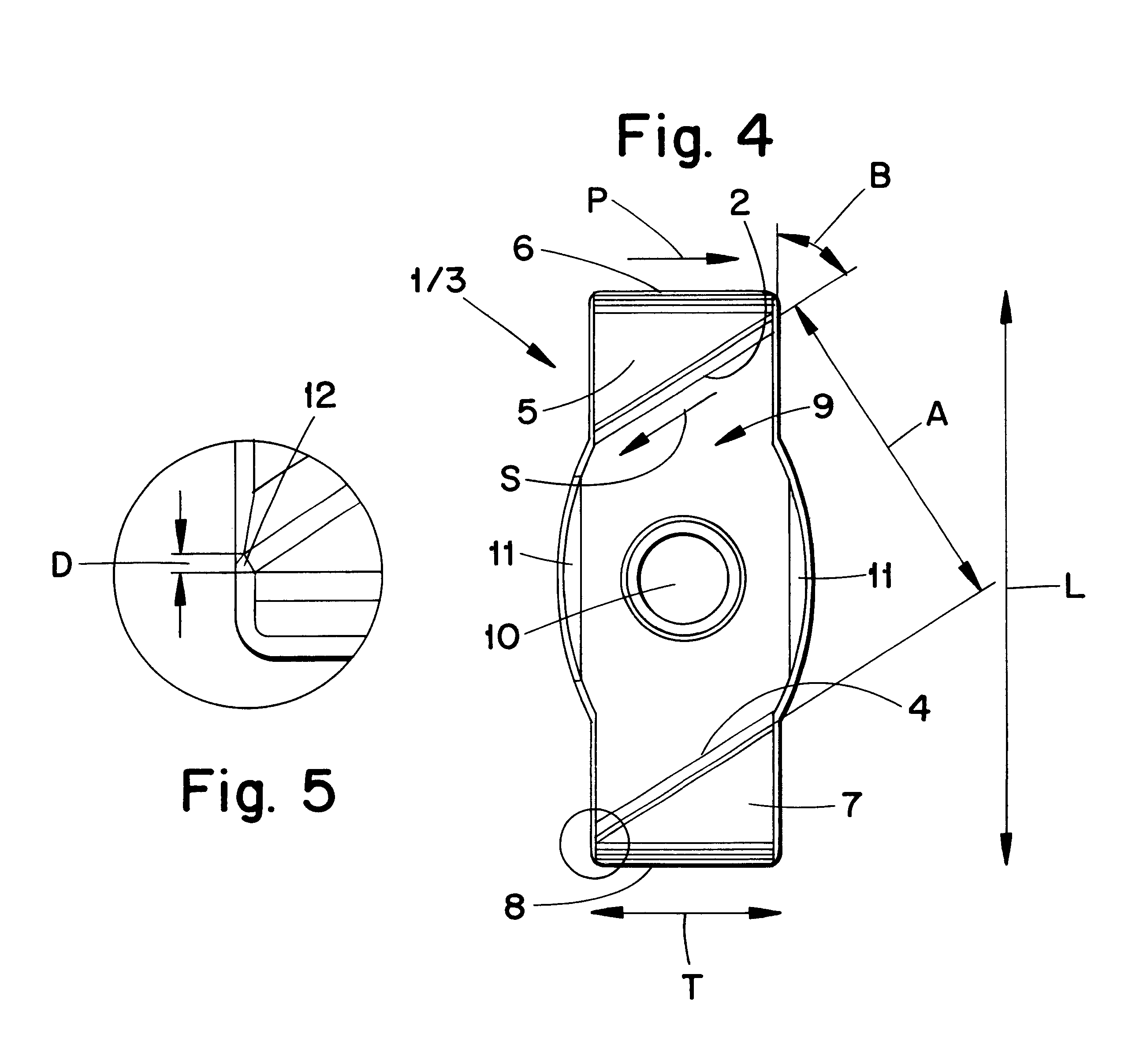
The support pad 1 / guide bar 3 (shown in FIGS. 2-4) is of a generally parallelepipedical basic shape and a generally rectangular shape in planar view, see FIG. 4. The support pad 1 / gui...
PUM
| Property | Measurement | Unit |
|---|---|---|
| Angle | aaaaa | aaaaa |
| Angle | aaaaa | aaaaa |
| Length | aaaaa | aaaaa |
Abstract
Description
Claims
Application Information