Scanner document speed encoder

a document speed encoder and scanner technology, applied in the direction of discharge tubes/lamp details, instruments, photoelectric discharge tubes, etc., can solve the problems of over-exposed images, under-exposed images, and many commercially available handheld document scanners without automatic exposure control

Inactive Publication Date: 2003-08-19
XEROS LTD
View PDF14 Cites 122 Cited by
  • Summary
  • Abstract
  • Description
  • Claims
  • Application Information

AI Technical Summary

Problems solved by technology

However, generally real-time capture of information using a PDA requires manual entry of data either using a miniaturized keyboard, or by cursive writing with a stylus on the PDA.
Also, many commercially available handheld document scanners lack an automatic exposure control.
If the scanner moves too slowly, the image will be over-exposed.
If the scanner moves too fast, the image will be under-exposed.
Repetitively scanning a document to obtain an acceptable image is very time consuming and frustrating.
In addition to severe technological constraints of small physical size, extremely high optical performance, and low electrical power consumption, there also a severe price constraint for document scanners to be used with PDAs.

Method used


Image

  • Scanner document speed encoder
  • Scanner document speed encoder
  • Scanner document speed encoder

Examples


Embodiment Construction

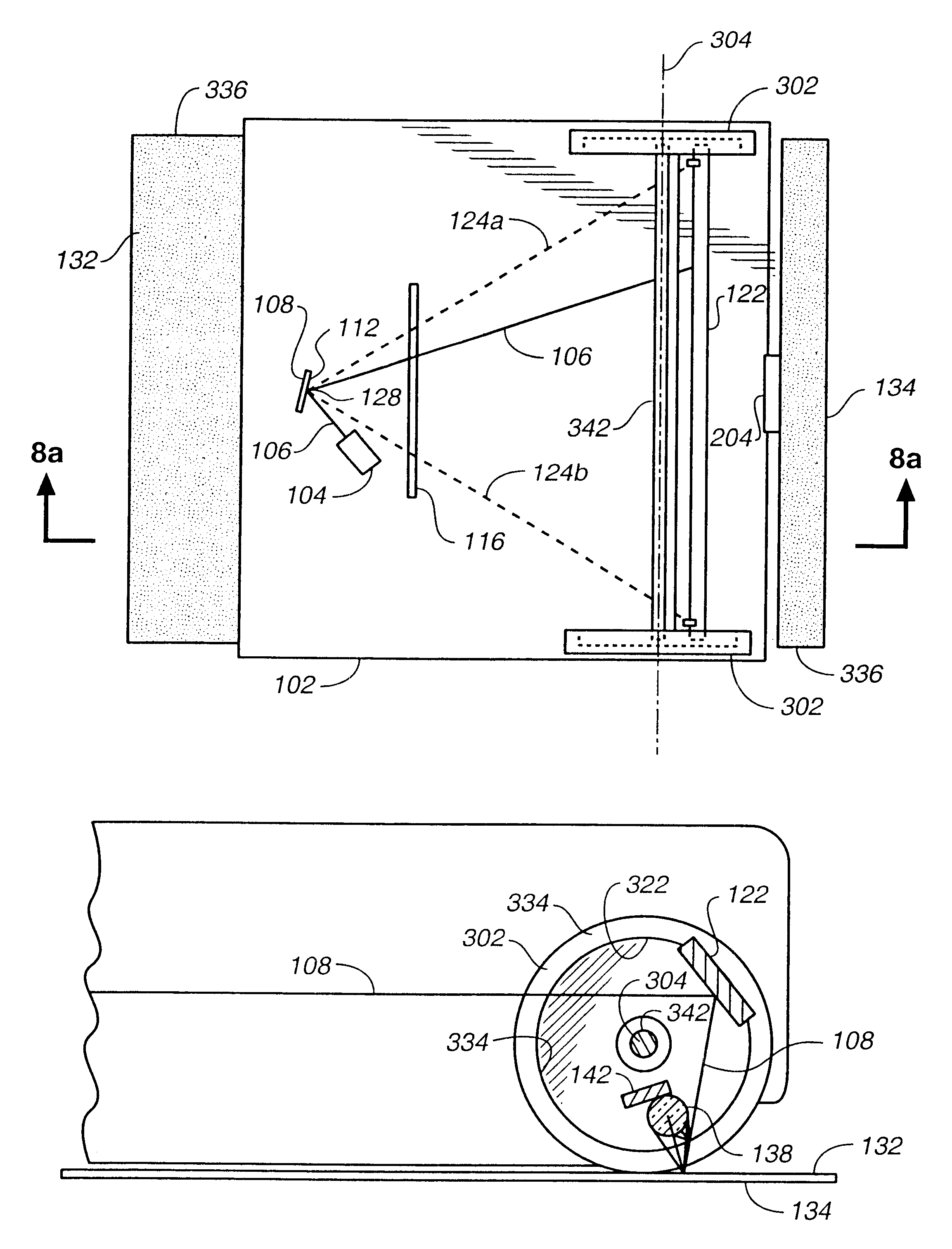
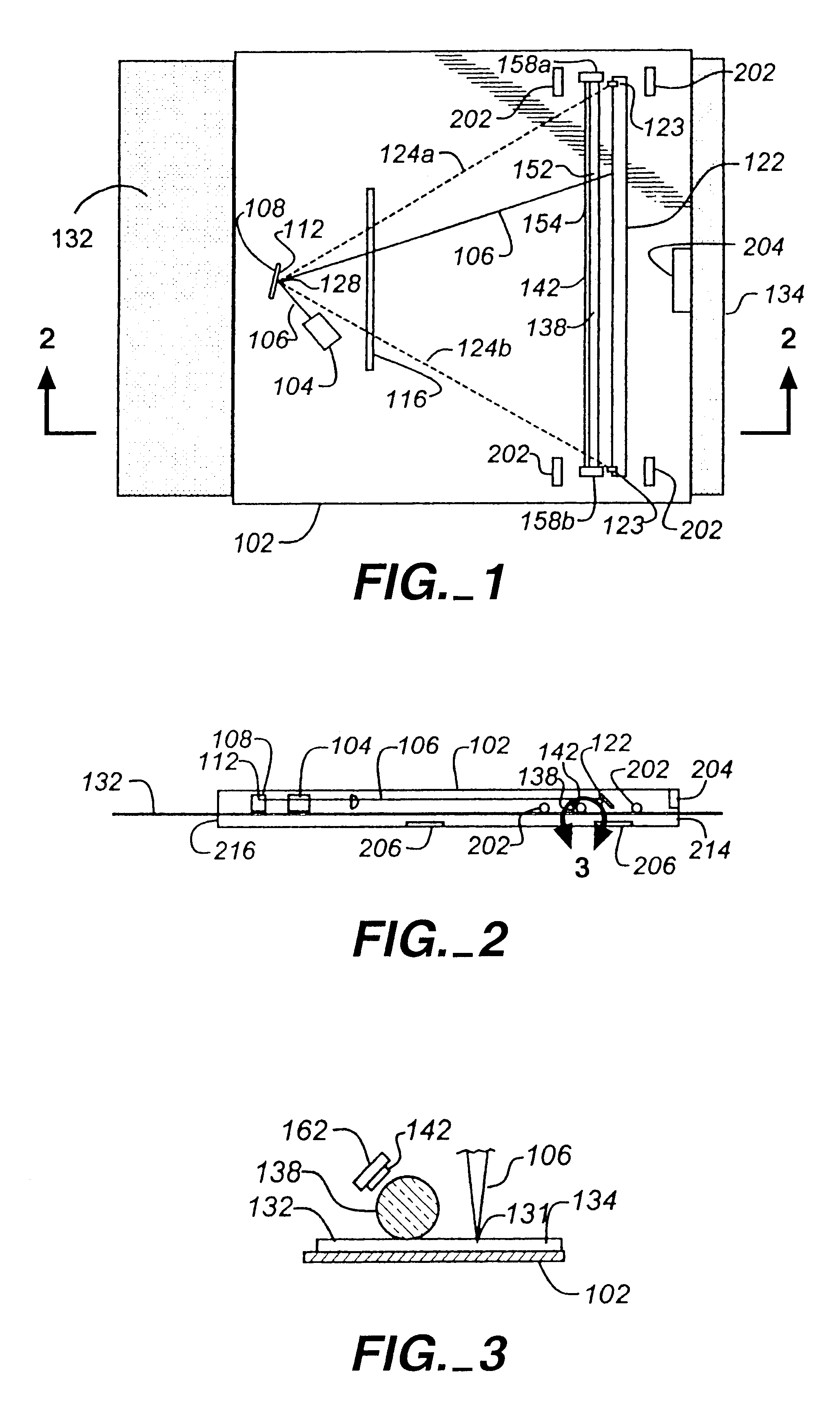
FIG. 1 illustrates a compact document scanner in accordance with the present invention referred to by the general reference character 100. The document scanner 100 depicted in FIG. 1 is more thoroughly described in Patent Cooperation Treaty ("PCT") international patent application WO / 23800 published Jul. 3, 1997, that is incorporated herein by reference ("the PCT published patent application"). The document scanner 100 includes a housing 102 that encloses a light source 104, preferably a laser diode together with optics for focusing a beam of light 106 emitted by the laser diode, or some other light source.

Also fixed within the housing 102 is a silicon micromachined torsional scanner 108 that includes a reciprocating mirror plate 112. The beam of light 106 preferably impinges directly upon the mirror plate 112 upon emission from the light source 104. The torsional scanner 108 is preferably constructed in accordance with the description set forth in U.S. Pat. No. 5,629,790 entitled "...


PUM


Abstract

A scanner, through which a document moves while being scanned by a moving beam of light, includes a wheel that rotates responsive to document movement. The wheel includes a multi-sectioned optical encoder upon which the scanning beam of light impinges when in a position at which it does not impinge upon the document. The scanner also includes an optical detector which receives light that is not absorbed by the optical encoder sections. Thus, the optical detector generates an electrical signal that indicates document movement speed. A preferred embodiment the scanner includes a pair of cup-shaped wheels one of which carries the optical encoder that encircles an inner surface of the wheel adjacent to a lip thereof. An axle, also included in the preferred embodiment, spans between, is coupled to, and supports the wheels for rotation in unison about a longitudinal axis parallel to the axle.

Description

1. Field of the InventionThe present invention relates to the field of documents scanners and, more particularly but not exclusively to document scanners used with notebook and laptop computers and personal digital assistants (PDA's).2. Description of the Prior ArtHistorically, document scanners have been large, flatbed, desktop devices that occupy a footprint on a worksurface having an area which is larger than the largest document to be scanned, e.g. larger than 81 / 2.times.11 inches. Smaller, sheet-fed document scanners have been developed in which during scanning a document travels along a U-shaped or curved path through the document scanner. Also document scanners have been developed in which a handheld wand is drawn across the surface of a document. All three of the preceding types of document scanners, i.e. flatbed scanners, curved path scanners, and wand scanners, have been connected by a signal and power cable usually to a desktop computer. Because a desktop working environm...

Claims


Application Information

Patent Timeline
Patent Type & Authority Patents(United States)
IPC IPC(8): H04N1/12H04N1/107H04N1/193H04N1/191H04N1/00
CPCH04N1/00689H04N1/00891H04N1/0476H04N1/107H04N1/1072H04N1/1078H04N1/121H04N1/00885H04N1/193H04N2201/0096H04N2201/0471H04N2201/04732H04N2201/04737
Inventor NEUKERMANS, ARMAND P.DOWNING, JAMES P.SLATER, TIMOTHY G.
Owner XEROS LTD
Why Eureka
Try Eureka