Primary frequency regulation method in combined-cycle steam turbines

a technology of combined-cycle steam turbines and frequency regulation methods, which is applied in the direction of steam engine plants, combined combustion mitigation, jet propulsion plants, etc., can solve the problems of not being able to adjust the amount of energy, the response time of this order of magnitude is not useful to achieve pfr, and the problem of steam turbines in combined-cycle with gas turbines posing a quite different problem

Inactive Publication Date: 2003-08-26
PETROBRAS ENERGIA
View PDF17 Cites 28 Cited by
  • Summary
  • Abstract
  • Description
  • Claims
  • Application Information

AI Technical Summary

Problems solved by technology

On the contrary, steam turbines in combined cycles with gas turbines pose a quite different problem.
Response times of this order of magnitude are not useful to attain PFR because, as stated above, response times of several seconds are necessary.
Unlike conventional cycle steam turbines, in combined cycle steam turbines it is not possible to adjust the amount of energy fed into the boilers at will.
Consequently, steam turbines in combined cycle facilities are usually excluded from the network's PFR, and this degrades the quality of power currently delivered by combined cycles.
However, the use of an additional combustion system in combined cycle plants originates in economic criteria unrelated to PFR, and only a small number of such plants make use of this system.
On the other hand, due to unstable combustion as well as other technical considerations, it is not common to find combined cycle plants with additional combustion systems that provide PFR service in their steam turbines.
Sometimes combined cycle plants that are required to provide PFR service do so only with their gas turbines due to the difficulties encountered to comply with this requirement for steam turbines.
However, none of these operational modes is efficient.
However, such loss of power generated by the steam turbine is completely useless, because the combined cycle plant will generate less power and the managers of the system will not consider it as Spinning Reserve for PFR purposes.
It is generally accepted that any throttling of the steam turbine control valves would cause a dramatic loss in output power, as well as introduce instability in the process, because the steam turbine would not be using all of the steam generated in the heat recovery boiler.
This idea has frequently led combined cycle plant manufacturers and operators to think that the provision of PFR by means of steam turbines in combined cycle plants is not practical.
As explained above, when gas turbines provide PFR, a certain amount of power from the steam turbine is lost because the gas turbines must operate below their rated capacity.
Under conventional prior art methods, the Spinning Reserve created in the steam turbine is not readily available by the network as required by the PFR.
This response time is not acceptable to achieve PFR in the system, since, as stated above, response times of just a few seconds are required.
On the contrary, any such losses are negligible and thus very difficult to measure.
However, this is not a major obstacle against the application of the present method, since the operation of the associated gas turbines in PFR mode, together with the decrease in output power in the steam turbine, both cause a decrease in steam pressure.
However, if a certain degree of throttling in the control valves is exceeded, the behavior of the system will no longer be the one depicted in FIG. 2.
If, even under these conditions, the maximum working steam pressures are reached, but the desired amount of Spinning Reserve useful for PFR is not achieved, then the amount of Spinning Reserve useful for PFR of the steam turbine shall be limited to the maximum value attainable.
However, these latter changes are not precisely predictable, since there is not a univocal relationship between the aperture of the steam turbine control valves and the corresponding output power.
Therefore, when operating with PFR under this mode, the actual contribution of these turbines to the control of the mains frequency cannot be predicted accurately.
This is indeed not welcome by the authorities in charge of power dispatch.
Both situations would cause poor performance of the PFR function, and would also cause instability in the power generation process, like over-pressures or sharp changes in system parameters.

Method used


Image

  • Primary frequency regulation method in combined-cycle steam turbines
  • Primary frequency regulation method in combined-cycle steam turbines
  • Primary frequency regulation method in combined-cycle steam turbines

Examples


Embodiment Construction

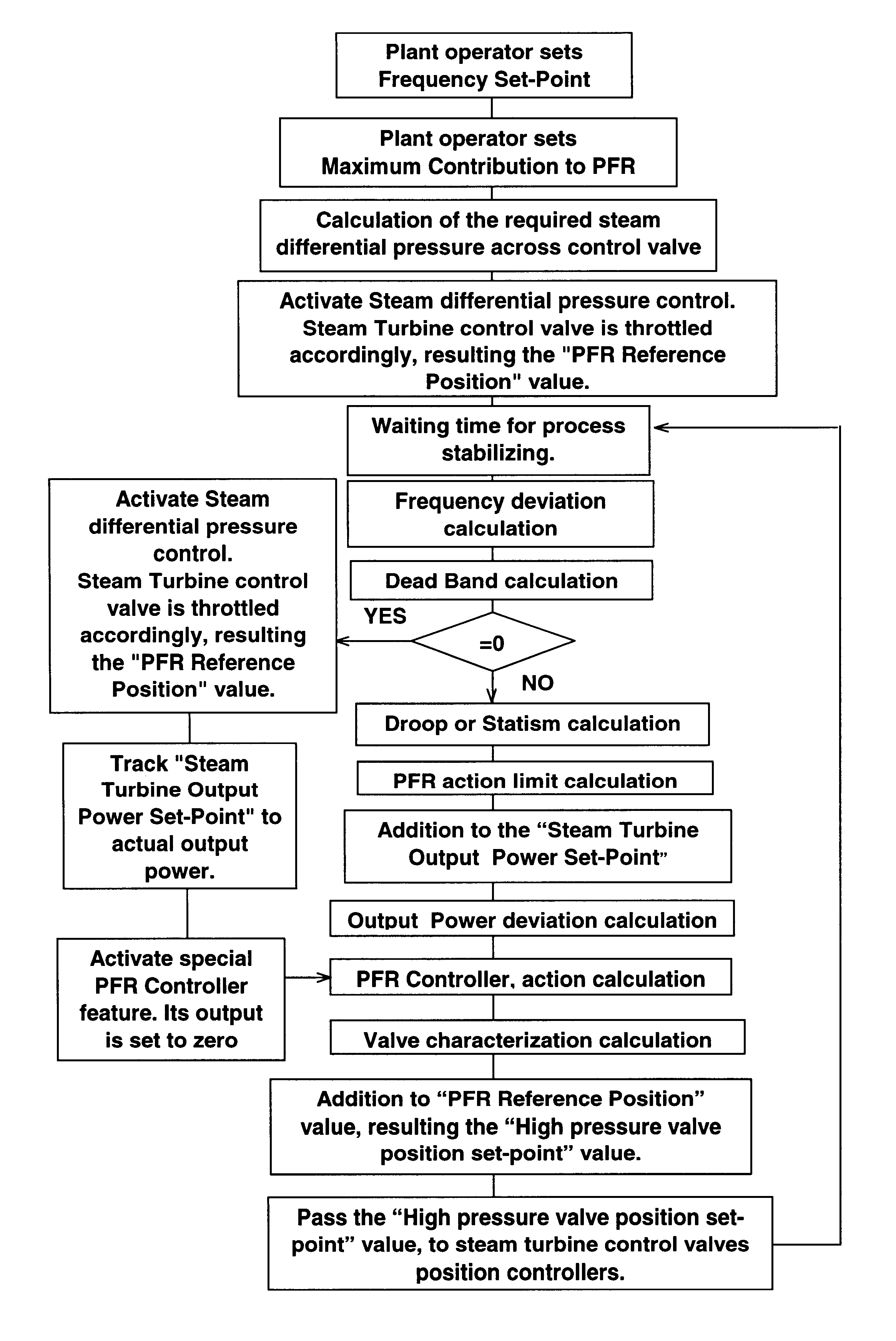
FIG. 4 illustrates a general block diagram of the method, and FIG. 5 is a flowchart showing the steps of the method.

The plant operator must in the first place fix the value of two parameters according to the requirements. One of these parameters is "Frequency Set Point." Frequency Set Point is the desired value for frequency, which normally is set as the rated frequency of the system. The second parameter that the operator must determine is "Maximum Contribution to PFR". Maximum Contribution to PFR is the absolute value of the maximum output power that PFR will contribute to control the mains frequency. This second value is determined by the operator on the basis of the local regulatory requirements for PFR in the system.

Once the "Maximum Contribution to PFR" value has been set, the block "Reference Position for PFR" calculates the degree of throttling of the control valves that is necessary to obtain such an increase in output power, whenever needed. In order to determine the throt...


PUM


Abstract

A method to provide Primary Frequency Regulation to a steam turbine in a combined cycle plant that comprises storing energy in the form of internal energy of the steam contained within the piping and domes of the heat recovery boilers, and then using said energy when the power grid requires a sudden increase in output power. With the present method, the losses in power generation of the steam turbine, when said turbine is operating in the Primary Frequency Regulation mode, are reduced to a minimum. When the gas turbines in a combined cycle plant operate in PFR mode, the steam turbine reduces its output power because the gas turbines must operate below their rated power. The present method converts said decrease in output power of the steam turbine in a Spinning Reserve useful for PFR in said turbine. That is to say that the present method converts said Spinning Reserve in a rapid reserve, available after just a few seconds; if necessary, response times of less than 10 seconds can be attained. The present method introduces several novel steps, which constitute its essence, said steps permitting the continuous, long term operation of the steam turbine in a combined cycle plant in PFR mode, thereby ensuring at any time the effectiveness of mains frequency regulation and also guaranteeing the stability of the power generation process in said combined cycle plant.

Description

This application claims the benefit of Argentine Patent Application No. P 01 01 03353, filed on Jul. 13, 2001.The present invention relates to a method for providing Primary Frequency Regulation in the steam turbines of combined-cycle power generation plants, such plants comprising at least one gas turbine and at least one steam turbine.PRIOR ARTBefore the development of the present invention, most power generators associated with steam turbines forming part of combined cycle plants based on gas turbines were not capable of being provided with the type of control known in the art as Primary Frequency Regulation (PFR). PFR is a function required by the agencies in charge of dispatch in power networks of many countries and is considered to be one of the parameters characterizing the quality of power delivered to customers.The problem to be solved in steam turbines of combined cycle power plants is basically that the steam turbine is unable to supply significant amounts of additional p...

Claims


Application Information

Patent Timeline
Patent Type & Authority Patents(United States)
IPC IPC(8): F01K23/10F01D15/10F01D17/24
CPCF01K23/101Y02E20/16
Inventor VUGDELIJA, JORGE
Owner PETROBRAS ENERGIA
Why Eureka
Try Eureka